Do you have a question about the Hirschmann RSP 20 and is the answer not in the manual?
General advice for safe operation of the device, including handling, storage, and maintenance.
Specifies the necessary training, knowledge, and experience for personnel working with the device.
Defines the intended applications and operational conditions for the device as described in the manual.
Ensuring electrical installation meets local or nationally applicable safety regulations.
Procedures and importance of establishing a separate ground connection for the device.
Guidelines for connecting the correct working voltage, including specifications and safety precautions.
Information and requirements for connecting the signal contact for remote diagnosis.
Specifies suitable locations, such as fire-protected enclosures or switch cabinets, for device installation.
Rules regarding opening the device housing, ventilation, and handling at high temperatures.
Details European directives compliance for the devices and the manufacturer's address.
Explains the meaning of symbols used throughout the manual for clarity.
Overview of the RSP 20/25/30/35 device's features, variants, and industrial automation suitability.
Explains how device names and product codes are structured based on defined characteristics.
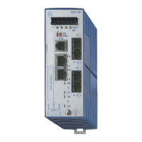
Details available device variants and their configurable options for ports, temperature, and voltage.
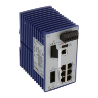
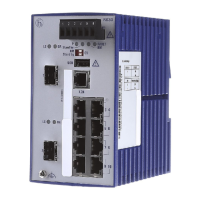
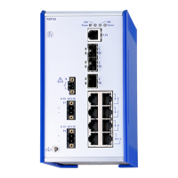
Illustrates the physical layout and identifies components on the front view of the device.
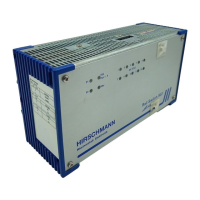
Information on the device's power supply characteristics (K9, KK, CC) and connection types.
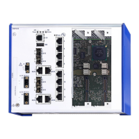
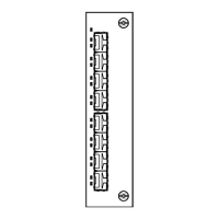
Description of different Ethernet port types (twisted pair, F/O) and their specifications.
Explanation of the LEDs indicating device status, ring manager, and storage medium status.
Details on V.24 serial interface and SD card interface for device management and configuration.
Describes the signal contact's functionality as a potential-free relay contact for remote diagnosis.
Procedure for verifying received items against the scope of delivery and checking for transport damage.
Steps for inserting and securing the AutoConfiguration Adapter ACA31 storage medium.
Instructions for mounting the device on a DIN rail and establishing a proper ground connection.
Guide on how to properly insert SFP modules into the device's SFP slots.
Procedures for connecting various terminal blocks for power supply and signal contacts.
Steps required to enable the working voltage and operate the device, including torque specifications.
Recommendations for connecting data cables in environments with high electrical interference levels.
Guidance on using the inscription label for identifying the device, often with its IP address.
Overview of the device's default IP address, management password, and port configurations.
Step-by-step instructions for safely removing the device from its mounting.
Guide on how to properly remove an SFP transceiver from the device's slot.
Provides essential specifications like dimensions, weight, and power supply details.
Visual representation of the device's physical dimensions in millimeters and inches.
Details on electromagnetic compatibility, immunity standards, and test results.
| Layer | Layer 2 |
|---|---|
| Jumbo Frame Support | Yes |
| Protection Class | IP30 |
| MAC Address Table | 8K |
| Operating Temperature | -40°C to 70°C |
| Storage Temperature | -40°C to +85°C |
| Mounting | DIN-rail |