Installation RSP 20/25/30/35
Release
08
08/2014
31
For every working voltage to be connected, perform the following steps:
Remove the power connector from the device.
Connect the protective conductor according to the pin assignment on the
device with the clamp.
Connect the wires according to the pin assignment on the device with the
clamps.
Fasten the wires connected by tightening the terminal screws.
With a non-redundant supply of the working voltage, the device reports the
loss of a working voltage. You can prevent this message by changing the
configuration in the Management.
2.5.3 Working voltage characteristic value CC
You will find information on the characteristic values here:
“Device name and product code” on page 13
You have the option of supplying the working voltage redundantly, without
load distribution.
Both working voltage inputs are uncoupled.
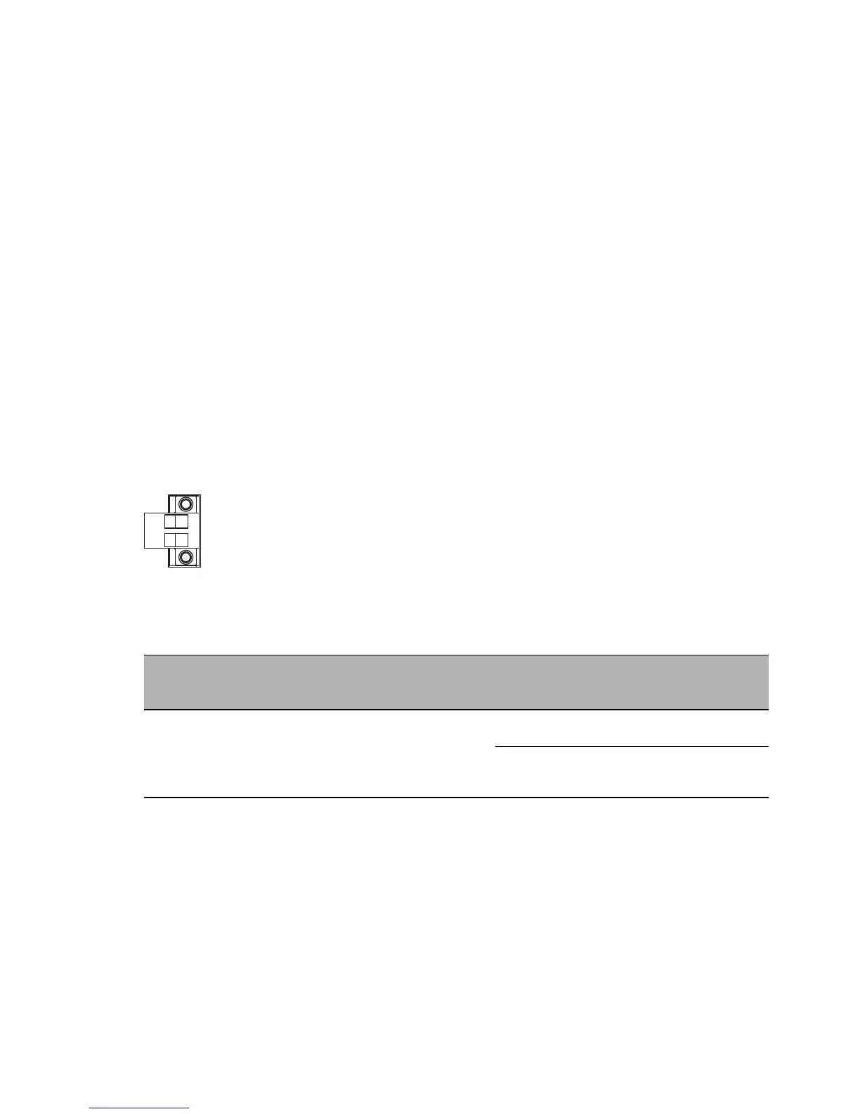
Figure 5: Working voltage characteristic value CC: 2-pin terminal block with screw
locking
For every working voltage to be connected, perform the following steps:
Remove the power connector from the device.
Connect the wires according to the pin assignment on the device with the
clamps.
Fasten the wires connected by tightening the terminal screws.
Type of the voltages
that can be
connected
Specification of the working
voltage
Connections
DC voltage Rated voltage range DC
24 V ... 48 V
Voltage range DC incl.
maximum tolerances
18 V ... 60 V
+ Plus terminal of the working
voltage
− Minus terminal of the working
voltage
Table 10: Working voltage characteristic value CC: type and specification of the
working voltage, connections