Do you have a question about the Hirschmann RS1 Series and is the answer not in the manual?
Outlines precautions for handling static-sensitive modules and preventing electrostatic discharge damage.
Explains the device's data frame handling, including store-and-forward and multi-address capabilities.
Covers building ring structures and redundant coupling of network segments.
Describes how to create a redundant ring network structure using the RM1.
Details the process of redundantly coupling multiple network segments.
| Brand | Hirschmann |
|---|---|
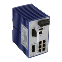
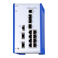
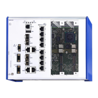
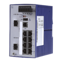
| Model | RS1 Series |
| Category | Switch |
| Language | English |