3
1. Functional description
The ports of an RS1/RM1 represent a termi-
nal connection for the connected LAN seg-
ment.
1.1 FRAME-SWITCHING FUNCTIONS
Store and Forward
All data received by the RS1/RM1 from the
system bus or at the ports are stored and
checked for validity. Invalid and defective
frames as well as fragments are discarded.
The RS1/RM1 forwards the valid frames.
Multi address capability
An RS1 learns all source addresses per port.
Only packets with
– this address or
– a multi/broadcast address
in the destination address field are sent to
this port.
An RS1 learns up to 8.000 addresses. This
becomes necessary if more than one termi-
nal device is connected to one or more
ports. In this way several independent sub-
networks can be connected to an RS1.
Learn addresses
An RS1 monitors the age of the learned
addresses. The RS1 deletes address entries
from the address table which exceed a cer-
tain age (10 seconds).
Note: Restarting deletes the learned
address entries.
Operation in duplex mode
Depending on the DIP switch setting of the
RS1 the 10 MBit/s ports 1 to 4 are in the half
or fullduplex mode. The 10 Mbit/s ports 5 to
8 are in the halfduplex mode.
Each 100 Mbit/s port is in the fullduplex
mode.
1.2 SPECIFIC FUNCTIONS OF THE
TP INTERFACE
Link control
The RS1/RM1 monitors the connected TP
line segments for short-circuit or interrupt
using regular link test pulses in accordance
with IEEE standard 802.3 10BASE-T. The
RS1/RM1 does not transmit any data in an
TP segment from which it does not receive
a link test pulse.
Note: A non-occupied interface is assessed
as a line interrupt. The TP line to terminal
equipment which is switched off is likewise
assessed as a line interrupt as the de-
energised bus coupler cannot transmit link
test pulses.
Auto polarity exchange
If the reception line pair is incorrectly
connected (RD+ and RD- switched) polarity
is automatically reversed.
1.3 SPECIFIC FUNCTIONS OF THE
F/O INTERFACE
Link control
According to IEEE 802.3 standard 100BASE-
FX an RS1/RM1 monitors the attached F/O
lines for open circuit conditions.
1.4 REDUNDANCY FUNCTIONS
Backbone as a ring
With an RM1 you can close a line structured
RS1 backbone to a redundant ring.
If one section fails the ring structure chan-
ges itself back into a line structure within
0.5 seconds at up to 50 RS1s.
Redundant coupling of segments
The built-in control intelligence of the RS1s
allows the redundant coupling of 10 MBit/s
network segments. Within 0.5 seconds an
error is detected and eliminated.
1.5 DISPLAY ELEMENTS
Equipment status
These LEDs provide information about sta-
tuses which affect the function of the entire
RS1/RM1s.
L1 – Line 1 (green LED)
– lit: – supply voltage 1 present
– lit not: – supply voltage 1 is less than 18 V,
– hardware fault in RS1/RM1
L2 – Line 2 (green LED)
– lit: – supply voltage 2 present
– lit not: – supply voltage 2 is less than 18 V,
– hardware fault in RS1/RM1
FDX – Fullduplex (Green LED, RS1)
– lit: – Full duplex mode
(10 MBit/s ports 1 to 4).
– lit not: – Half duplex mode
(10 MBit/s ports).
Stby – Standby (Green LED, RS1)
– lit: – The standby function is
enabled.
– lit not: – The standby function is
disabled.
CPU – System (Yellow/red LED, RM1)
– lit not: – Initializing, hardware self
test
– lit red: – Self test error
– flashes red (1 Hz):
– Loading software
– lit red with interruption:
– Writing to Flash EPROM
– lit yellow: – The User Interface (V.24)
is occupied
– flashes yellow (0,5 Hz):
– The system is initialized
and runs fault-free.
Port Status
These LEDs display port-related informati-
on.
DA/STAT – Data, Link status
(green/yellow LED)
– lit not: – no valid link
– lit green: – valid link
– blinking green (1 time in periodical inter-
val)
– port is switched to stand-
by (RS1, port 1, 2)
– blinking green (2 times in periodical inter-
val)
– port is autopartitioned
– blinking green (3 times in periodical inter-
val)
– port is disabled
– flashes yellow:– receiving data
1.6 CONTROLS
12-pin DIP switch (RS1)
10-pin DIP switch (RM1)
Using the 12-pin DIP switch on the top of
the RS1 housing and the 10-pin DIP switch
on the front panel of the RM1 housing
– the message about the link statuses can
be suppressed by the indicator contact on
a port-by-port basis. Using switches LA1
to LA6, the message about the link status
of ports 1 to 6 is suppressed. State on
delivery: switch position 1 (on), i.e. messa-
ge not suppressed.
– on RS1 the 10 MBit/s ports 1 to 4 can be
switched to the full duplex or half duplex
mode with the switch FDX. State of deli-
very: position 0 (Off), i.e. half duplex.
The 10 Mbit/s ports 5 to 8 are always in
the halfduplex mode.
– on RS1 the standby function can be enab-
led or disabled with the switch Stby .
State of delivery: position 0 (Off), i.e. nor-
mal function. In the redundant link run the
RS1 in the standby mode for redundant
coupling of 10 MBit/s network segments.
RS1 in the standby mode for redundant
coupling of 10 MBit/s network segments.
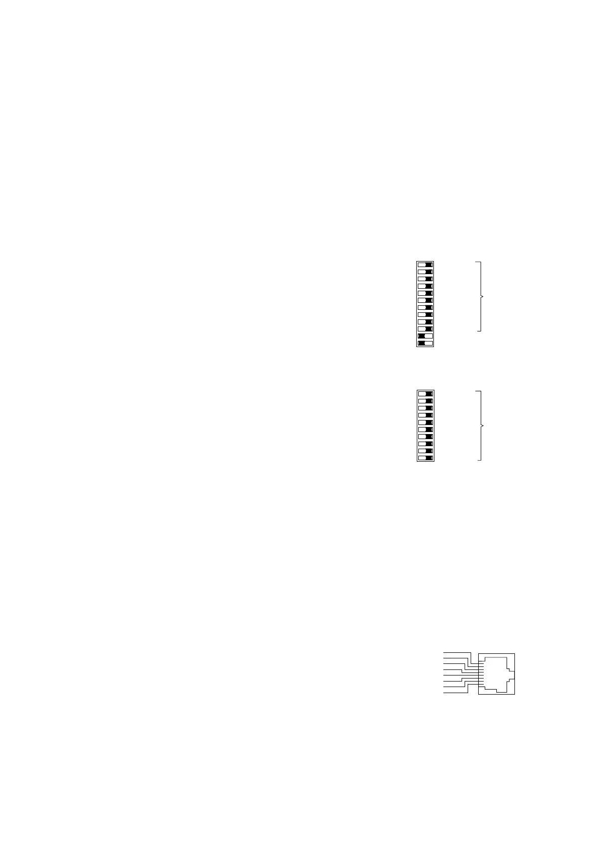
Fig. 1: 12-pin DIP switch on RS1
Fig. 2: 10-pin DIP switch on RS1
Reset push button (RM1)
Pushing the push button resets the RM1.
1.7 INTERFACES
10 Mbit/s connection
Eight 8-pin RJ45 sockets allow eight inde-
pendent TP segments to be connected. The
socket casings are electrically connected to
the front panel and thus connected to the
housing of the RS1/RM1.
– Pin configuration of the RJ45 socket:
– TD+: pin 3, TD-: pin 6
– RD+: pin 1, RD-: pin 2
– remaining pins: not configured.
Fig. 3: Pin configuration of an TP interface
 Loading...