4
supply voltage is electrically isolated from
the housing.
– Indicator contact: Contract interrupt
indicates the following by means of a
potential-free indicator contact (relay
contact, closed circuit):
– the failure of at least one of the two
supply voltages.
– a permanent fault in the RS1/RM1 (inter-
nal 5 V DC voltage, supply voltage 1 or 2
< 18 V).
– the faulty link status of at least one port.
The indication of the link state might be
masked on a port-by-port basis using
DIP switches (RS1).
– at least one port has auto partitioned.
– selft test error
RM1
– Ring monitoring is not possible, e. g.
during software initializing.
RS1 in normal mode
– short-circuited control line.
– partner device runs in normal mode.
RS1 in standby mode
– not attached, short-circuited or interrup-
ted control line.
– partner device runs in normal mode.
Note: In the case of the voltage supply
being routed without redundancy, the
RS1/RM1 indicates the failure of a supply
voltage. You can prevent this message by
feeding in the supply voltage through both
inputs.
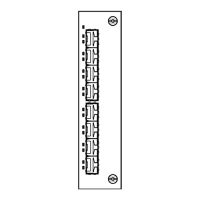
Fig. 5: Pin configuration of 5-pin terminal
block
+24 V
+24 V
Fault
L1+
L2+
M
F1
F2
100 Mbit/s connection
Two ports allow a 100 Mbit/s backbone to
be constructed.
– RS1-FX/FX: two ports in accordance with
100BASE-FX (SC sockets, multimode)
– RS1-TX/TX: two ports in accordance with
100BASE-TX (RJ45 sockets)
– RS1-TX/FX: one port in accordance with
100BASE-FX (SC socket, multimode) and
one port in accordance with 100BASE-TX
(RJ45 socket)
– RS1-TX/FX: one port in accordance with
100BASE-FX (SC socket, singlemode) and
one port in accordance with 100BASE-T
(RJ45 socket)
– RM1: two slots for 100 Mbit/s modules
with one port each:
ETSXM-01TP(FE) with TX port,
ETSXM-01MM(FE) with one FX port
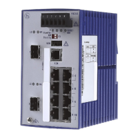
Standby-Port (RS1)
A 8-pin RJ45 socket serves for connecting
the control line for the redundancy mode.
The socket casing is electrically connected
to the front panel and thus connected to the
housing of the RS1s.
– Pin configuration of the RJ45 socket:
– Stby_Out+: Pin 3, Stby_Out-: Pin 6
– Stby_In+: Pin 1, Stby_In-: Pin 2
– remaining pins: not configured.
Fig. 4: Pin configuration of the standby
interface
5-pin terminal block
The supply voltage and the indicator
contact are connected via a 5-pin terminal
block with screw locking mechanism.
v
Warning!
The RS1/RM1 equipment is desi-
gned for operation with SELV. Only
safety extra-low voltages to
IEC950/EN60950/VDE0805 may
therefore be connected to the
supply voltage connections and to
the indicator contact.
– Voltage supply: The voltage supply can
be connected to be redundant. Both
inputs are decoupled. There is no load
distribution. With redundant supply, the
power pack supplies the RS1/RM1 alone
with the higher output voltage. The
n.c. Pin 8
n.c. Pin 7
Stby_Out- Pin 6
n.c. Pin 5
n.c. Pin 4
Pin 3Stby_Out+
Pin 2Stby_In-
Pin 1Stby_In+
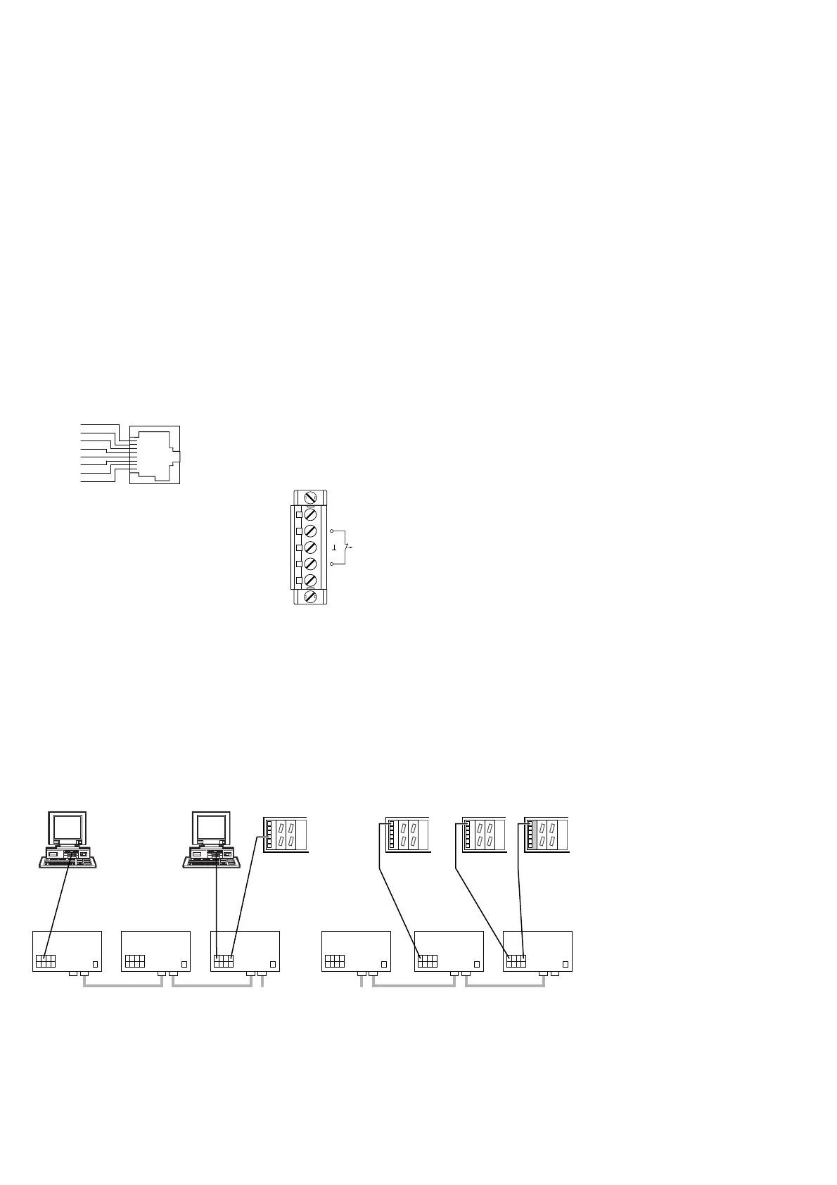
2. Configuration
2.1 LINE STRUCTURE
The RS1s enable backbones in line structu-
res to be built up. Cascading is effected
using the 100 Mbit/s ports (see Fig. 5).
2.2 REDUNDANT RING STRUCTURE
With an RM1 you can close the two ends of
a line structured backbone to a redundant
ring (see Fig. 6)
2.3 REDUNDANT COUPLING OF NET-
WORK SEGMENTS
The built-in control intelligence of the RS1
allows the redundant coupling of network
segments (see Fig. 7).
The connection of two network segments is
realized via two seperate paths with an RS1
each. The RS1 in the redundant line gets the
redundancy function assigned by the DIP
switch setting standby.
The RS1 in the redundant line and the RS1
in the main line share their operating states
via the control line.
After the failure of the main line the redun-
dant RS1 enables the redundant line imme-
diately. If the main line is okay again, the
RS1 in the main line informs the redundant
RS1 about this. The main line will be enab-
led and the redundant line will be disabled.