6
3. Assembly, startup procedure
and dismantling
3.1 UNPACKING, CHECKING
M Check whether the package was deliver-
ed complete (see scope of delivery).
M Check the individual parts for transport
damage.
v
Warning!
Use only undamaged parts!
3.2 ASSEMBLY
The equipment is delivered in a ready-to-
operate condition. The following procedure
is appropriate for assembly:
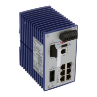
RS1
M Check whether the switch pre-setting
suits your requirements (see chap. 1.6).
M Pull the terminal block off the RS1 and
wire up the supply voltage and indicator
lines.
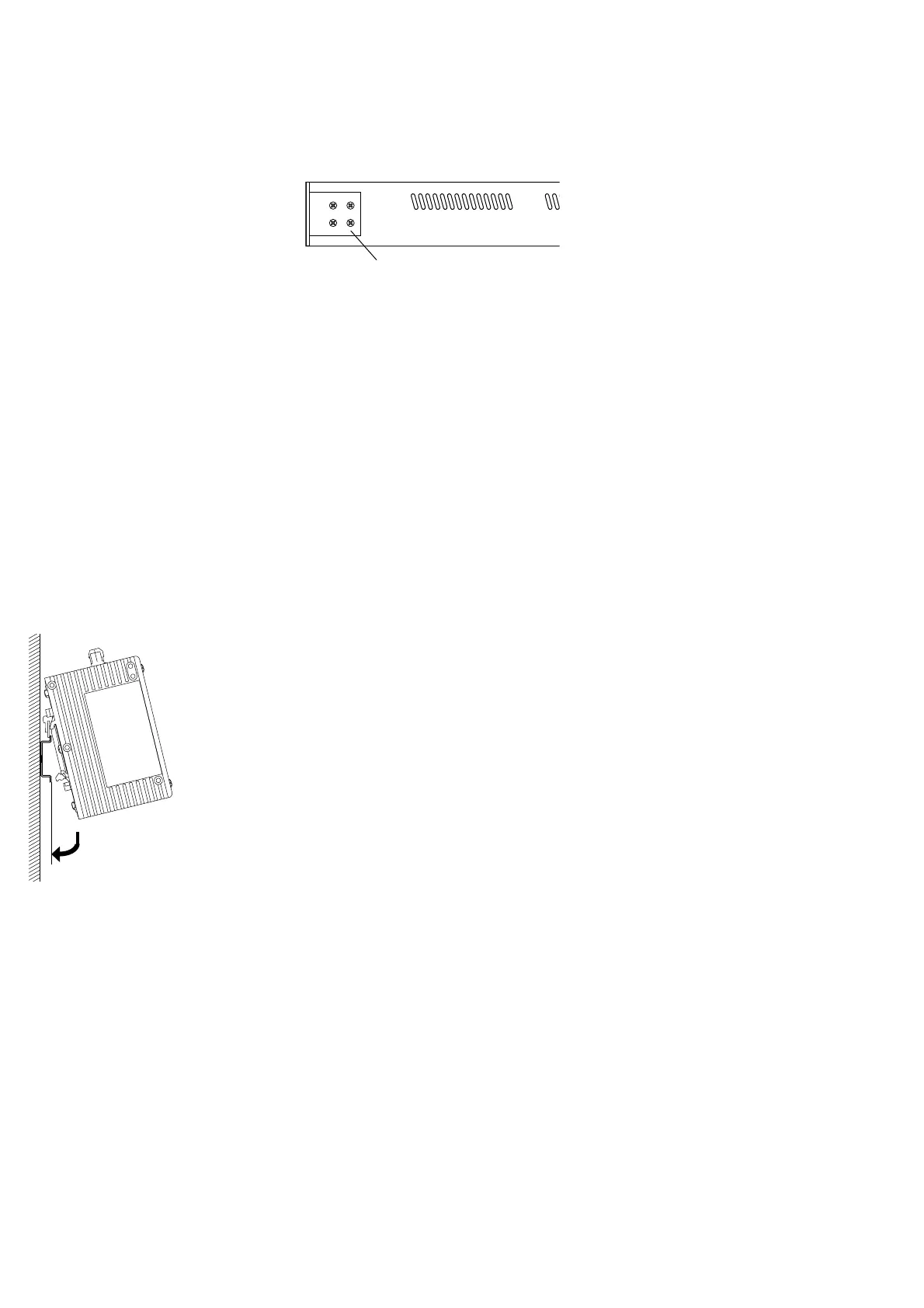
M Fit the RS1 on a 35 mm standard bar to
DIN EN 50 022.
M Suspend the upper snap-on slide bar of
the RS1 in the standard bar and press it
down towards the standard bar until it locks
in position.
M Fit the signal lines and if required the
control line.
Notes:
– The housing of the RS1 is grounded via
the standard bar. There is no separate
ground connection.
– Do not open the housing.
– The shielding ground of the twisted pair
lines which can be connected is electrical-
ly connected to the housing.
Fig. 9: Assambling the RS1
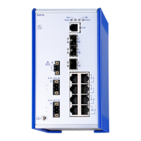
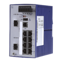
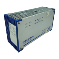
RM1
m Mounting the rubber feet
Stick the rubber feet supplied to the bottom
of the device in order to set it up as a desk-
top unit.
M Remove the backing from the adhesive
film of the rubber feet.
M Stick one rubber foot approx. 2 cm from
each corner of the device.
Note: The surface should be free of dust
and grease.
m Screwing on the mounting brackets
M Attach the mounting brackets supplied
as shown in Fig. 10:
M First loosen the four corresponding
screws on one side of the device
M Attach the first mounting bracket with
the 4 screws.
M Repeat on the other side.
Fig. 10: Fastening the mounting brackets
m Grounding the RM1´s
The housing of the RM1 is grounded via the
sperate grounding screw. It is on the device
back on the right next to the fan.
M Fasten the grounding cable on the
grounding screw.
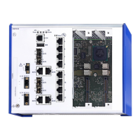
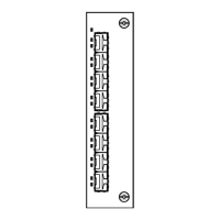
m Fitting with 100 Mbit/s modules
The modules can be plugged in and pulled
off the RM1 during operation (hot swapa-
ble).
M Be sure to observe the notes on ESD
protection on page 2.
M Choose a slot.
M Remove the blind panel of the RM1 so
that you are able to plug in the module.
M Push the module in the slot’s mounting
rails on the right and left side well fitting as
far as it will go.
M Screw
– the two thumbscrews in the
front panel of the module with
– the frame of the RM1.
m Connecting the RM1
M Check whether the switch pre-setting
suits your requirements (see chap. 1.6).
M Pull the terminal block off the RM1 and
wire up the supply voltage and indicator
lines.
M Fit the signal lines.
3.3 STARTUP PROCEDURE
You start up the RS1/RM1 by connecting the
supply voltage via the 5-pin terminal block.
Lock the terminal block with the locking
screw at the side.
3.4 DISMANTLING
To dismantle the RS1 from the standard bar,
pull the RS1 downwards and on the bottom
lift the RS1 away from the standard bar.
 Loading...