Installation RS20/22/30/32/40
Release
05
12/2015
27
Examples for product name
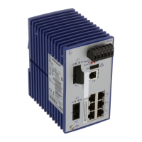
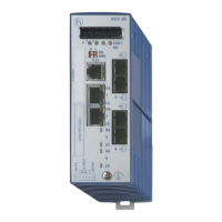
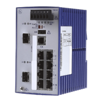
1.1.3 Number of ports and media for RS20-...
Figure 1: Device variants with 4 × 10/100 Mbit/s ports (RS20-0400...)
1 – plug-in terminal block, 6-pin
2 – LED display elements
3 – 2-pin DIP switch
4 – USB interface
5 – V.24 connection for external management
6 – ports in compliance with 10/100BASE-T(X) (RJ45 connections)
7 – port 1 + port 2, free choice of connections:
T1: Twisted-pair T(X), RJ45, 10/100 Mbit/s
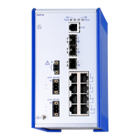
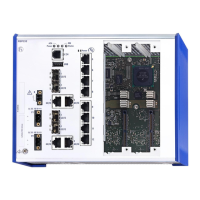
RS40-
RS40- Rail Switch with gigabit ports
00
00 0 × 100 Mbit/s Ethernet ports
09
09 9 × 1000 Mbit/s Ethernet ports
CC
CC Port 1 + 2 = Combo port: SFP slot (100/1000 Mbit/s),
alternatively: RJ45 connector (10/100/1000 Mbit/s)
CC
CC Port 3 + 4 = Combo port: SFP slot (100/1000 Mbit/s),
alternatively: RJ45 connector (10/100/1000 Mbit/s)
E
E Temperature range Extended (−40 °F to +158 °F; −40 °C to +70 °C )
with Conformal Coating
D
D Voltage range: 9.6 V DC to 60 V DC or 18 V AC to 30 V AC
A
A Approvals: CE, UL 508, ISA 12.12.01 (UL 1604)
P
P Software variant: Professional
Table 6: Example of RS40 with 4 uplink ports: RS40-0009CCCCEDAP
RS20
RM
Stand by
Aufkleber MAC-Adresse
IP-ADDRESS
V.24
USB
P
Stand by
FAULT
RM
ON
LS
1
DA
LS
2
DA
LS
3
DA
LS
4
DA
1
2
3
4
5
6
7
7
8
9
RS20-0400T1T1...D... RS20-0400M2T1...D...
RS20
RM
Stand by
Aufkleber MAC-Adresse
IP-ADDRESS
V.2 4
USB
P
Stand by
FAULT
RM
ON
1
LS
2
DA
LS
3
DA
LS
4
DA
RS20
RM
Stand by
Aufkleber MAC-Adresse
IP-ADDRESS
V.2 4
USB
P
Stand by
FAULT
RM
ON
1
2
LS
3
DA
LS
4
DA
RS20-0400M2M2...D...
LS
1
DA
LS
2
DA
LS
1
DA
+24V(P1) 0V 0V
FAULT
+24V(P2)
+24V(P1) 0V 0V
FAULT
+24V(P2) +24V(P1) 0V 0V
FAULT
+24V(P2)
 Loading...