Redundant coupling
36
3.2
Configuring the redundant coupling
Redundancy L2E
Release
4.1
03/08
Note: Operating the redundancy manager and two-Switch coupling functions
at the same time runs the risk of creating a loop.
Note: The following settings are required for the coupling ports (you
select the Basic Settings:Port Configuration dialog):
– Port: on
– Automatic configuration (autonegotiation):
on for twisted-pair connections
– Manual configuration: 100 Mbit/s FDX
for glass fiber connections
Note: If VLANS are configured, note the VLAN configuration of the
coupling and partner coupling ports.
In the Network/Ring Coupling configuration, select for the coupling and
partner coupling ports
– VLAN ID 1 and “Ingress Filtering” disabled in the port table and
– VLAN membership U in the static VLAN table.
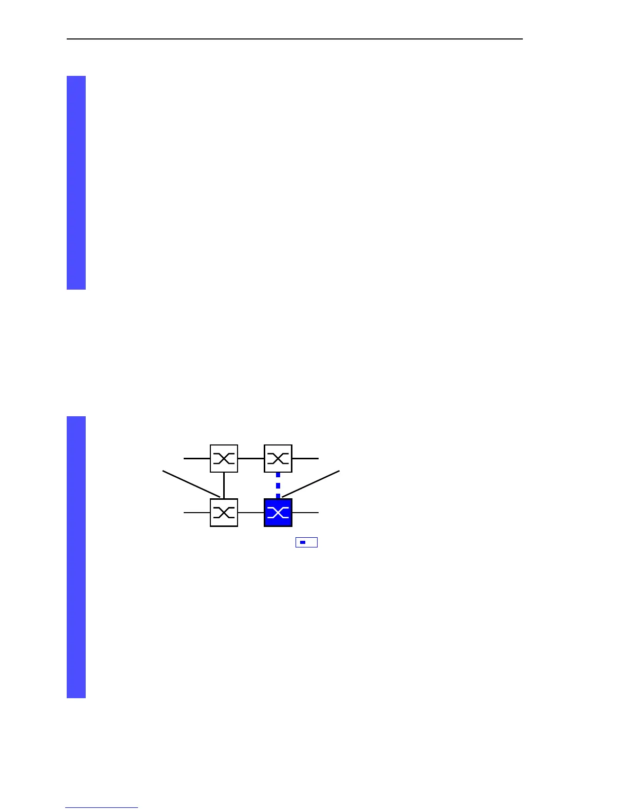
Select two-Switch redundant coupling (see fig. 16).
Figure 16: Two-Switch coupling
The following settings apply to the Switch displayed in blue in the
selected graphic.
Select the coupling port (see fig. 15), (see table 9).
With “Coupling port” you specify at which port you are connecting
the network segments.
If the STANDBY DIP switch is ON, connect the main line to the
coupling port.