Redundant coupling
Redundancy L2E
Release
4.1
03/08
3.2
Configuring the redundant coupling
35
Note: Configure the coupling port and the HIPER-Ring ports on different
ports.
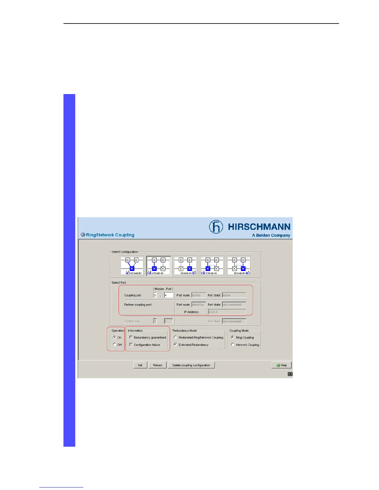
Activate the function in the “Operation” frame (see fig. 15).
You now connect the redundant line.
The displays in the “Select port” frame mean (see fig. 15):
– “Port mode”: The port is either active or in stand-by mode.
– “Port state”: The port is either connected or not connected.
– “IP Address”: The IP address of the partner, if the partner is already
operating in the network.
The displays in the “Information” frame mean (see fig. 15):
– “Redundancy guaranteed”: One of the lines affected can fail, as a
redundant line will then take over the function of the failed line.
– “Configuration failure”: The function is incomplete or incorrectly
configured.
Figure 15: Selecting the port and enabling/disabling operation
To avoid continuous loops, the Switch sets the port state of the coupling
port to “off” if you:
– switch off operation or
– change the configuration
while the connections are in operation at these ports.