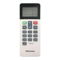
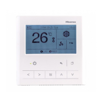
Wireless Receiver Kit
(2) Insert the cable into the rigid metal conduit.
(3) Fix the fixing bracket of kit by using screw
(Field-Supplied).
This figure shows the case of Switch Box for 1 Controller.
(4) Attach the cover same as A-(4).
Cable
Screw (Field-Supplied)
Box (Field-Supplied)
(Step 2)
Click Sound.
Check to ensure that
cable is not loosen.
(Step 1)
Hooking Part
Cover
(5)Remove the cover of indoor unit electrical control box and connect the cable to the terminals A and B of
the terminal board (white).
Printed Circuit Board
Te r minal Board
(White)
Mark Band "A"
Mark Band "B"
Cable for Wireless Receiver Kit
Example
Electrical Box
for Indoor Unit
After connecting the cable, bind up the remaining cable length portion by band (Factory-Supplied)
and put them in the electrical control box.
Then install the expanded PCB。
The install of expanded PCB refer to step (6).
Cable
NOTES:
Protective box recommend size 99.5 by 92.5 by 35 mm,
fixed hole center is 78 mm.
Receiver panel with transparent plastic protective film,
the official may required removed
according to user.
Remove the cover by using slotted screwdriver.
When the back cover installation, to tidy up wiring,
attention to the back cover marked \"switch\"
that justify the board of SW1 switch position
If not according to the requirements of sequenced
operations,may cause install or remove substrate difficulties.
 Loading...