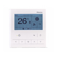
Wireless Receiver Kit
●
B
A
B
A
Fig. 3
●
●
●
(6)
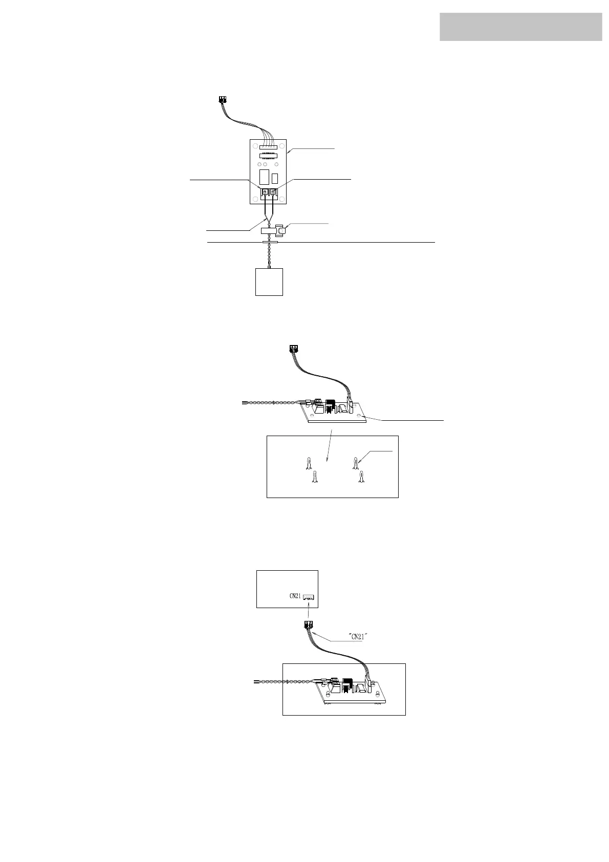
The install of expanded PCB :
As shown in figure 1 below. Connect the receiver kit to terminal CN23 of the expanded PCB.
terminal CN23
expanded pcb
Clamp
receiver kit
torque 0.5N
Inside of electrical box
Outside of electrical box
Fig. 1
As shown in figure 2. In the electrical box there are four spare white supporting feet, arranging for 63 mm × 26 mm
rectangle.Set the extended pcb up to these four white support feet.
Inside of electrical box
Installation holes
support feet
Twisted Pair
Fig. 2
As shown in figure 3 .Connect the bring wiring of the expanded pcb (labeling CN21) to the terminal
CN21 of master pcb.
master pcb
Inside of electrical box
lable
Using clamp tighten twisted-pair .
 Loading...