4
STANDARD ACCESSORIES
(1) 255 mm TCT Saw blade (mounted on tool) .............1
(2) Dust bag ......................................................................1
(3) 10 mm Box wrench ....................................................1
(4) Vise Assembly ............................................................1
(5) 4 mm Hex.bar wrench (only C10FCH) ......................1
(6) Sub Fence...................................................................1
(7) Collar (A) (D30) ...........................................................1
Standard accessories are subject to change without notice.
OPTIONAL ACCESSORIES (SOLD SEPARATELY)
(1) Extension Holder and Stopper
(2) Crown molding Vise Ass'y (Include Crown molding
Stopper (L))
(3) Crown molding Stopper (L)
(4) Crown molding Stopper (R)
Optional accessories are subject to change without notice.
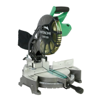
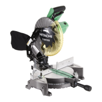
APPLICATION
䡬 Cutting various types of aluminium sash and wood.
UNPACKING
䡬 Carefully unpack the power tool and all related items
(standard accessories).
䡬 Check carefully to make certain all related items
(standard accessories) are present.
PRIOR TO OPERATION
1. Power source
Ensure that the power source to be utilized conforms
to the power requirements specified on the product
nameplate.
2. Power switch
Ensure that the power switch is in the OFF position. If
the plug is connected to a receptacle while the trigger
switch is in the ON position, the power tool will start
operating immediately, inviting serious accident.
3. Extension cord
When the work area is removed from the power
source, use an extension cord of sufficient thickness
and rated capacity. The extension cord should be kept
as short as practicable.
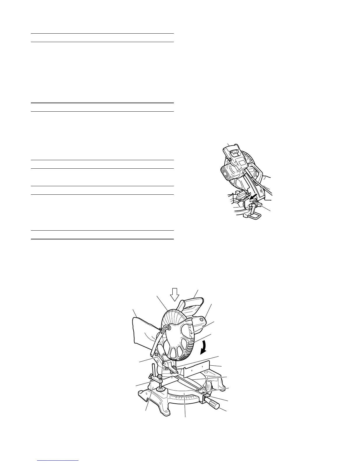
4. When the power tool is prepared for shipping, its
main parts are secured by a locking pin
Move the handle slightly so that the locking pin can
be disengaged.
During transport, lock the locking pin into the gear
case (Fig. 1).
Fig. 1
5. Attach the dust bag to the main unit (Fig. 2)
(1) When the dust bag has become full of sawdust, dust will
be blown out of the dust bag when the saw blade rotates.
Check the dust bag periodically and empty it before it
becomes full.
Locking Pin
Fig. 2
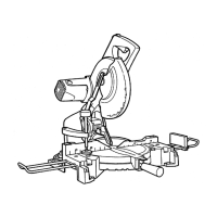
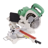
Handle
Motor Head
Turn table
Dust Bag
Vise Assembly
Fence (B)
Motor
Lever
Fence (A)
Saw Blade
Lower Guard
Gear Case
Laser Marker
Side Handle
Indicator (A) (For miter scale)
Table Insert
Indicator (B) (For bevel scale)
Handle

 Loading...