5
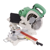
(2) During bevel and compound cutting, attach the dust bag
at a right angle to the base surface as shown in Fig. 3.
Fig. 3
CAUTION
䡬 Empty the dust bag frequently to prevent the duct and
the lower guard from becoming clogged.
Sawdust will accumulate more quickly than normal
during bevel cutting.
6. Installation
Ensure that the machine is always fixed to bench.
Attach the power tool to a level, horizontal work bench.
Select 8 mm diameter bolts suitable in length for the
thickness of the work bench.
Bolt length should be at least 35 mm plus the thickness
of the work bench.
For example, use 8 mm × 60 mm bolts for a 25 mm
thick work bench.
ADJUSTING THE POWER TOOL PRIOR TO USE
CAUTION
Make all necessary adjustments before inserting the
plug in the power source.
1. Check to see that the lower guard operates smoothly
PRACTICAL APPLICATIONS
WARNING
䡬 To avoid personal injury, never remove or place a
workpiece on the table while the tool is being operated.
䡬 Never place your limbs inside of the line next to
warning sign while the tool is being operated. This
may cause hazardous conditions (see Fig. 4).
Fig. 4
CAUTION
䡬 It is dangerous to remove or install the workpiece
while the saw blade is turning.
䡬 When sawing, clean off the shavings from the turntable.
䡬 If the shavings accumulate too much, the saw blade
from the cutting material will be exposed. Never
subject your hand or anything else to go near the
exposed blade.
1. Tightly secure the material by vise assembly to be
cut so that it does not move during cutting
2. Switch operation
Pulling the trigger turns the switch on. Releasing the
trigger turns the switch off.
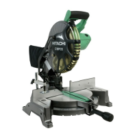
3. Holder (B) adjustment (Fig. 5)
Loosen the 6 mm bolt with the supplied 10 mm box
wrench. Adjust the holder (B) until its bottom surface
contacts the bench or the floor surface.
Fig. 5
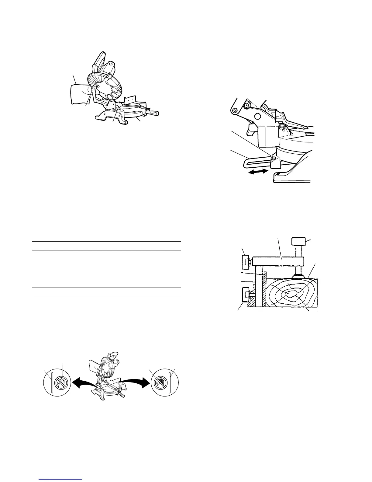
4. Using the Vise Assembly (Standard accessory) (Fig. 6)
(1) The vise assembly can be mounted on either the left
fence {Fence (B)} or the right fence {Fence (A)} by
loosening the 6 mm wing bolt (A).
Fig. 6
(2) The screw holder can be raised or lowered according
to the height of the workpiece by loosening the 6 mm
wing bolt (B). After the adjustment, firmly tighten the
6 mm wing bolt (B) and fix the screw holder.
(3) Turn the upper knob and securely fix the workpiece
in position.
WARNING
䡬 Always firmly clamp or vise to secure the workpiece
to the fence; otherwise the workpiece might be thrust
from the table and cause bodily harm.
CAUTION
䡬 Always confirm that the motor head does not contact
the vise assembly when it is lowered for cutting. If
there is any danger that it may do so, loosen the 6
mm wing bolt and move the vise assembly to a
position where it will not contact the saw blade.
Dust Bag
Duct
Right Angle
Base
Line
Warning
Sign
Warning
Sign
Line
6 mm Bolt
Holder (B)
6 mm Wing Bolt (B)
Screw Holder
Knob
Vise Plate
Workpiece
6 mm Wing Bolt (A)
Vise Shaft
Fence (B)
 Loading...