33
English
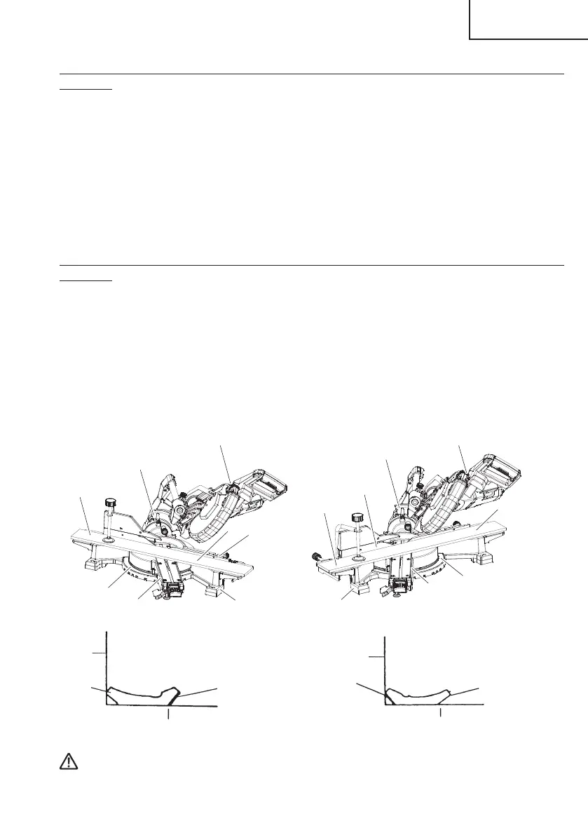
(3) Setting to cut crown moldings at positions 1 and 4 in Fig. 32 (see Fig. 37; tilt the head to
the right):
1 Turn the turntable to the right and set the Miter Angle as follows:
* For 45° type crown moldings: 35.3°
* For 38° type crown moldings: 31.6°
2 Tilt the head to the right and set the Bevel Angle as follows:
* For 45° type crown moldings: 30°
* For 38° type crown moldings: 33.9°
3 Position the crown molding so that the upper surface (Ⓑ in Fig. 31) contacts the fence
as indicated Fig. 39.
(4) Setting to cut crown moldings at positions 2 and 3 in Fig. 32 (see Fig. 38; tilt the head to
the right):
1 Turn the turntable to the left and set the Miter Angle as follows:
* For 45° type crown moldings: 35.3°
* For 38° type crown moldings: 31.6°
2 Tilt the head to the right and set the Bevel Angle as follows:
* For 45° type crown moldings: 30°
* For 38° type crown moldings: 33.9°
3 Position the crown molding so that the lower surface (Ⓐ in Fig. 31) contacts the fence
as in Fig. 40.
Fig. 37
Fence (A)
Base
Miter angle scale
Turntable
Bevel angle scale
Head
4
1
Turntable
Fig. 38
Head
Bevel angle scale
3
Miter angle scale
Base
Fence (B)
2
Fig. 40
Fence
Ⓐ
Ⓑ
Table on base
Fig. 39
Fence
Ⓐ
Ⓑ
Table on base
WARNING: Always fi rmly clamp or vise to secure the crown molding to the
fence; otherwise the crown molding might be thrust from the
table and cause bodily harm.
000BookC10FSHC(T)NA.indb33000BookC10FSHC(T)NA.indb33 2019/02/2516:34:132019/02/2516:34:13

 Loading...