20
English
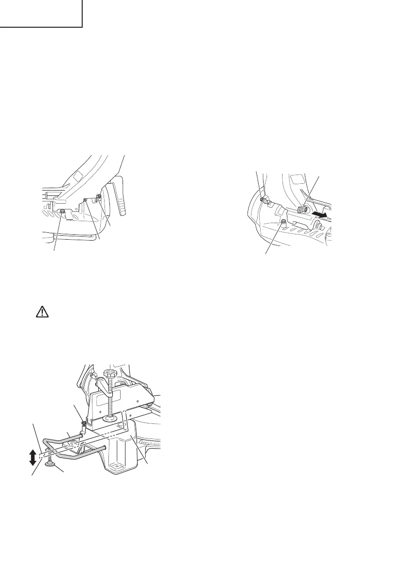
6. Oblique angle
Before the power tool is shipped from the factory, it is adjusted for 0°, right angle, left 45°
bevel cutting angle and right 45° bevel cutting angle with the 8 mm set screw, 8 mm bolt (A)
and 8 mm bolt (B).
When changing the adjustment, change the height of the 8 mm set screw, 8 mm bolt (A), or
8 mm bolt (B) by turning them.
When changing the bevel angle to the right 45°, pull the set pin (A) on the direction shown in
Fig. 12-b and incline the motor head to the right.
When adjusting the motor head to 0°, always return the set pin (A) to its initial position as
shown in Fig. 12-b.
Fig. 12-a
8 mm bolt (A)
(Stopper for left 45° bevel angle)
Indicator
(For left bevel scale)
Fig. 12-b
Pull
Set pin (A)
8 mm bolt (B)
(Stopper for right 45° bevel angle)
8 mm set screw
(Stopper for 0° not shown)
Indicator
(For right bevel scale)
7. Securing the workpiece
WARNING: Always clamp or vise to secure the workpiece to the fence;
otherwise the workpiece might be thrust from the table and cause
bodily harm.
8. Installing the holders ... (Optional accessory)
The holders help keep longer workpieces
stable and in place during the cutting operation.
(1) As indicated in Fig. 13, use a steel square
for aligning the upper edge of the holders
with the base surface.
Loosen the 6 mm wing nut. Turn a height
adjustment bolt 6 mm, and adjust the
height of the holder.
(2) After adjustment, fi rmly tighten the 6 mm
wing nut and fasten the holder with the
6 mm knob bolt (optional accessory). If the
length of Height Adjustment Bolt 6 mm is
insuffi cient, spread a thin plate beneath.
Make sure the end of Height Adjustment
Bolt 6 mm does not protrude from the
holder.
6 mm knob bolt
(Optional accessory)
Holder
(Optional
accessory)
Steel
square
Base surface
6 mm wing nut
(Optional
accessory)
Height adjustment bolt 6 mm
(Optional accessory)
Fig. 13
0000BookC12RSH2.indb200000BookC12RSH2.indb20 2016/03/0118:07:322016/03/0118:07:32
 Loading...