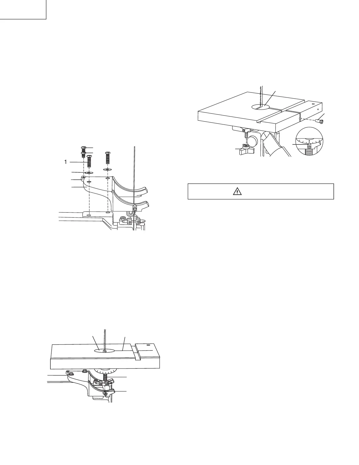
13. Place a lock knob (16) on each scale knob bolt
adjust the table by aligning the zero scale mark to
the scale pointer (17), and tighten the knob.
14. Replace the table insert (13), aligning the indents.
15. Place the table aligning pin (18) in the hole at the
front of the table, and tighten.
INSTALLING AND REMOVING THE BLADE (FIG. G)
To avoid injury from accidental starting, always turn the
switch OFF and remove the plus from the power source
before moving, replacing, or adjusting the blade.
1. Loosen the blade tension by turning the blade
tension knob (1) counterclockwise.
2. Remove the table insert (2) and the table aligning
pin (3) from the table. Unlock the lock knobs (12)
under the table. Unfasten the screw (13) at the right
of extension tube and remove the extension table
3. Open up wheel cover door (4).
4. Loosen the two Phillips screws (5) and remove the
5. Release the lock knobs (12) under the table, then
remove the screw (13) at the right of extension tube
6. Remove the blade (7) from the upper and lower
7. Carefully pull the blade from the side slot (9) and
8. Swing the left side of the blade toward you, turning
the blade so it will fi t through the slot (11) in the
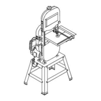
ASSEMBLE THE BAND SAW TABLE
Mounting the trunnion support bracke
1. Remove the two hex head bolts (1) and washers (2),
located on the lower band saw housing.
2. Place the trunnion support bracket (3) on the saw
body, as shown, aligning the mounting holes.
3. Place the washers on the hex head bolts, and insert
into the threaded holes, through the bracket and saw
Thread a nut (4) onto the table stop bolt (5) and
screw bolts into the rear tab (6) on the trunnion
5. Tighten the nut down onto the bracket tab.
. Turn the table right side up.
Remove the table insert (13) from the table.
Guide the table slot (14) over the saw table and
rotates 1/4 turn, so the slot is perpendicular to the
Placing the scale lock knob bolts (10) through the
trunnion bracket holes (15) as shown, lower the table
onto the trunnion bracket.
 Loading...