English
13
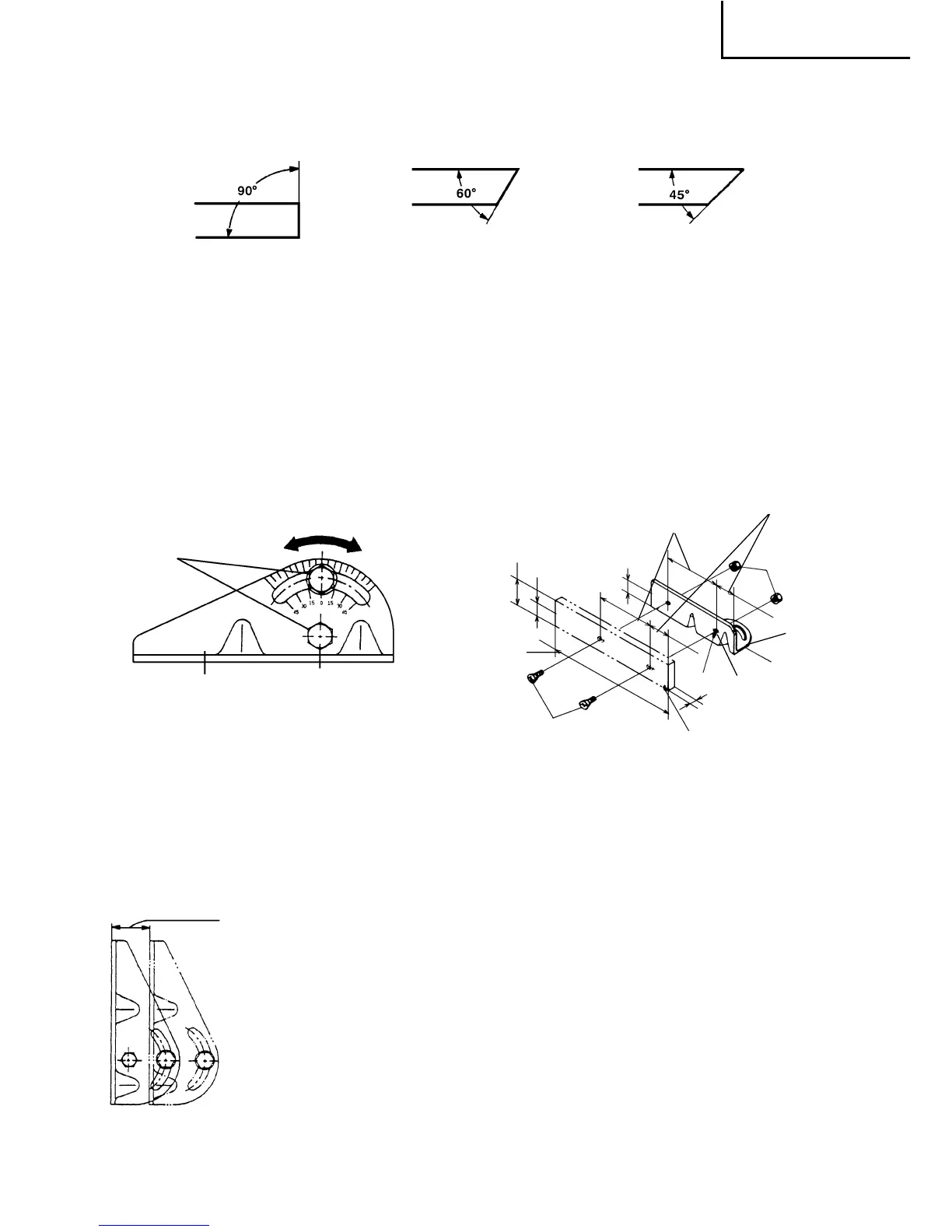
4. Cutting at angles (Fig. 7 and 8).
The machine permits cutting at angles of 45° or 60°
Fig. 7
Loosen the two 25/64" (10 mm) bolts on the vise (B), then set the working surface on the
vise-jaw at any angles of 0°, 30° or 45° as shown in Fig. 7.
Upon completion of setting, securely tighten the two 25/64" (10 mm) bolts, as shown in
Fig. 8.
When setting at an
angle of 0°
When setting at an
angle of 30°
When setting at an
angle of 45°
Fig. 8 Fig. 9
When wide material is to be cut at an angle, it should be firmly clamped by fixing a steel
board like Fig. 9 to the vise (B), as shown in Fig. 9.
5. Moving the stationary vise-jaw (Fig. 10).
The vise opening is set at the maximum of 5-15/
64"(133mm) when shipped from the factory.
In case an opening more than 5-15/64"(133mm) is
required, move the vise-jaw to the position shown
by the chain line, after unscrewing the two bolts.
The maximum opening can be set in two steps 6-
13/16"(173mm) and 8-3/8"(213mm).
When the material to be cut is excessively wide, the
vise can be effectively used by repositioning the
stationary side of the vise jaws.
Fig. 10
25/64"
(10 mm)
Vise (B)
The vise jaws open
to 5-15/64" (133 mm)
while the vise can
be set in two steps
6-13/16" (173 mm)
and 8-3/8" (213 mm)
Flat hd. screw of more than
15/64" × 19/32" (6 mm × 15)
8-27/64"
(214 mm)
2-11/64" (55 mm)
1-5/64" (27.5 mm)
1-5/64" (27.5 mm)
4-23/32"
(120 mm)
1-49/64"
(45 mm)
15/64"
(6 mm) nut
Vise (B)
Two holes 1/4"
(6.5 mm)
More than 15/64"
(6 mm)
Steel
board






 To Next Page