2. Installation Work
A16381TMF2
5
(2) Attach the controller to the holding bracket and connect the cable as follows.
1. In Case of Exposing the Controller Cable
c. Cut away the insulation at the end of the cable and clamp the M3 solderless terminals (eld-supplied).
(3) Attach the controller body to the mounted holding bracket. Be careful not to pinch the cable when attaching
it.
a. Prepare the optional eld-supplied Implanted Junction Box.
2. When Using Junction Box
Optional M-size
Junction Box
M4 Screws
Optional S-size
Junction Box
Connect the te
B
A
Remove the
protective film.
b. Feed the cable through the conduit tubing in the wall.
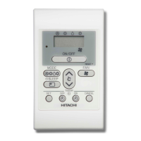
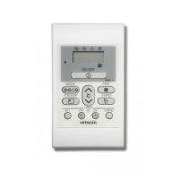
(4) After installation, remove the protective film from the LCD screen.
Stopper
-Supplied)
Cable
D. Attach the stopper (plastic band
to the cable at the inside of
the draw-out hole.
Draw-out Hole
C. Feed the cable with its
sheath peeled through
B. Peel away the insulation
at the end of the cable
and clamp the M3 (field-
supplied) solderless
terminals .
B
A
A. Secure the holding bracket
onto the wall with screws
(accessory)

 Loading...