--- 15 ---
(2) Reassembly of the clutch unit
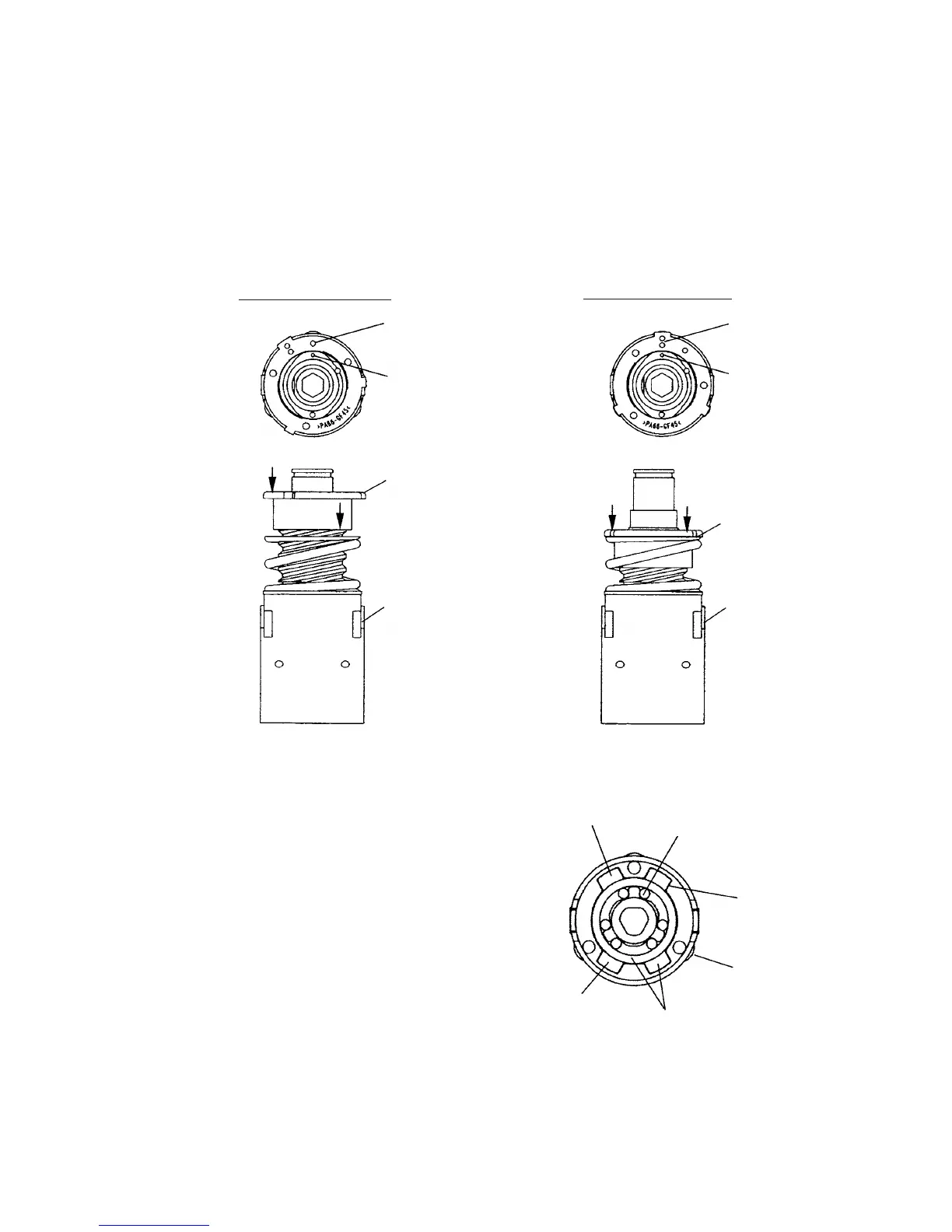
(a) Mount Washer (D) [9] and the Spring [8] to the Gear Case [11].
(b) Mount the Nut [7] to the Gear Case [11]. (See Fig. 4.)
Align the register mark (i) on the Nut [7] with the register mark on the Gear Case [11]. Turn the Nut [7]
about 1-1/12 turns clockwise so that the register mark (ii) on the Nut [7] is aligned with the register mark on
the Gear Case [11]. Check that the Y surface of the Nut [7] is aligned with the Z surface of the Gear Case
[11].
Fig. 4
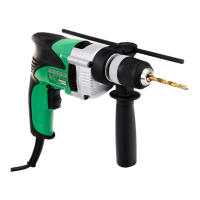
(3) Reassembly of the manual tightening mechanism
(a) Mount the Lock Ring [15] to the Gear Case [11]
so that the protrusion of the Lock Ring [15] alignes
with the concave portion of the Gear Case [11].
At this time, mount the Lock Ring [15] so that the
stepped protrusion faces forward.
(b) Mount the Needle Roller Set (6 pcs.) [16].
NOTE: Do not apply grease to the Lock Ring [15]
and the Needle Roller Set (6 pcs.) [16].
Nut [7]
Gear Case [11]
Y surface
Z surface
Register mark (i)
Mounting end position
Mounting start position
Register mark
Nut [7]
Gear Case [11]
Y surface
Z surface
Register mark (ii)
Register mark
Needle Roller Set
(6 pcs.) [16]
Lock Ring [15]
Concave portion
Gear Case [11]
Stepped portion
Protrusion
Fig. 5