--- 19 ---
Fig. 13
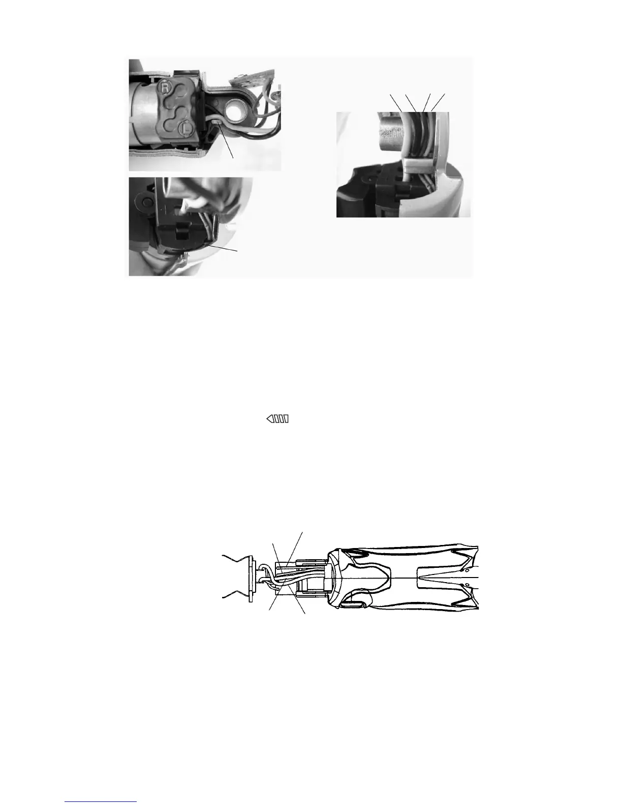
Black Red
(d) Close Housing (A).(B) Set [32] and mount the Handle Cover [43]. Tighten the four Pan Hd. Tapping Screws
D3 x 8 [33].
(e) Mount the two Click Plates [35] to Housing (A).(B) Set [32] and apply grease (Hitachi Motor Grease
No. 29).
(f) Check for proper operation of the Clutch Dial [6].
When the reassembly procedure is completed up to step (e), ensure that every indication on the Clutch Dial
[6] from number "1" to the drill mark " " can be aligned with the triangle mark on Housing (A).(B) Set
[32] respectively and that the Clutch Dial [6] turns moderately. If any indication on the Clutch Dial [6] cannot
be aligned with the triangle mark on Housing (A).(B) Set [32], correctly remount the Clutch Dial [6]
according to step (2) (b) as it is improperly mounted.
(g) Check that the internal wires of the Switch (W/Lock) [40] do not intersect with the internal wires of the LED.
(See Fig. 14.)
(8) Reassembly of the handle unit
Mount either of Handle (A).(B) Set [49] to Housing (A).(B) Set [32]. Fit the Printed Circuit Board [41] and the
Terminal Support [46] in the grooves of the handle. (See Fig. 15.) Mount the Button [45] to the switch of the
Printed Circuit Board [41] and close Handle (A).(B) Set [49]. Tighten the Tapping Screw (W/Flange) D4 x 20
(Black) [37]. Mount the two Clips [48] to the groove of Handle (A).(B) Set [49] using a flat-blade screwdriver.
Fig. 14
Do not pinch the intenal wires.
Rib
Red Black
Internal wire of the LED (Red)
Internal wire of the LED (Black)
Internal wire of
the switch (Red)
Internal wire of the
switch (Black)
(LED)
(Switch)