-14-
Spring [7]
Convex feature of Nut [6]
Matching mark on
Gear Case [9]
Matching mark on
Gear Case [9]
Surface Y
Nut [6]
Gear Case [9]
Surface Z
Spring [7]
Thrust Plate [8]
Surface Y Surface Z
Gear Case [9]
Nut [6]
Thrust Plate [8]
Convex feature of Nut [6]
Position to start screwing Position to stop screwing
x Fitting of the Click Spring
xReassembly of the drive unit
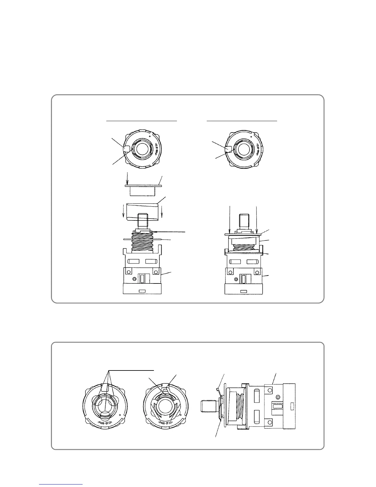
2. Reassembly of the drive unit
(1) Fit Thrust Plate [8] and Spring [7] sequentially onto Gear Case [9].
(2) Align the most convex feature of Nut [6] with the matching mark on Gear Case [9] as shown in the figure
below, and then screw in the nut.
Turn Nut [6] clockwise about 360 degrees, and then align the convex feature of Nut [6] with the matching
mark on Gear Case [9] as shown in the figure below. Confirm that surface Y of Nut [6] and surface Z of
Gear Case [9] are almost at the same level.
(3) While aligning the matching mark on Gear Case [9] with the projecting part of Click Spring [5], fit Click
Spring [5] into the notches on Gear Case [9]. Be sure to orient Click Spring [5] correctly as shown in the
figure below.
Matching mark
Projecting part
Three notches
Gear Case [9]
Projecting part
Click Spring [5]
 Loading...