-16-
Wider concave
feature
Convex
feature
Convex
feature
Wider convex
feature
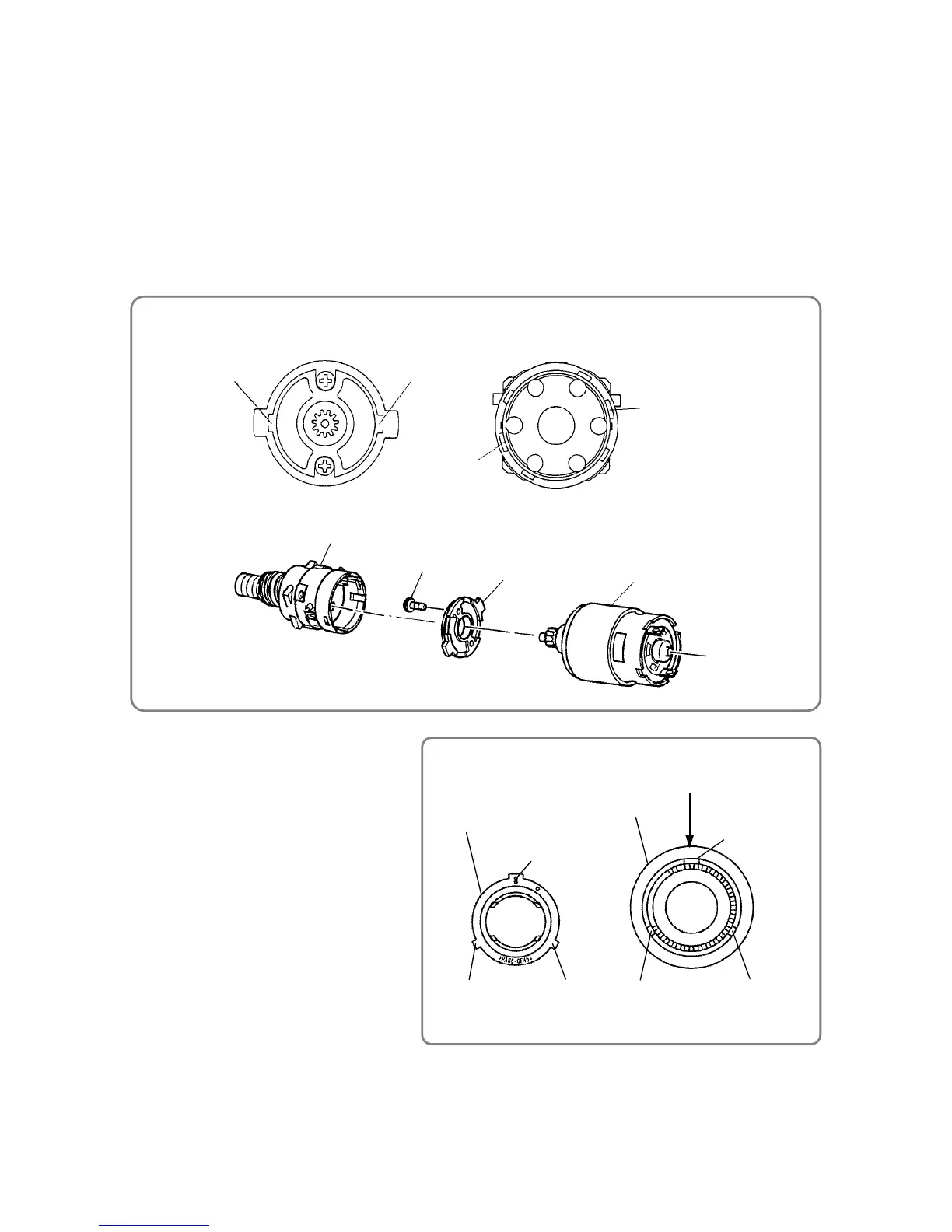
Nut [6]
Indication of "1"
Concave
feature
Concave
feature
Clutch Dial [4]
xReassembly of the Clutch Dial
x Coupling of the power supply unit with the drive unit
4. Coupling of the power supply unit with the drive unit
(1) Attach Motor Spacer [27] to Motor DC12V [28].
Fit the mounting screw of Motor DC12V [28] into the mounting hole of Motor Spacer [27], and then
secure the motor spacer with two Machine Screw M3 X 8 [26].
(2) Fit the convex feature of Motor Spacer [27] into the concave feature of Gear Case [9], and then turn
Motor Spacer [27] clockwise to secure it in place.
When attaching Motor DC12V [28] to Gear Box Ass’y [3], be careful to correctly orient Motor DC12V [28]
and Gear Case [9].
Once Motor DC12V [28] is mounted in the housing, the red marking on Motor DC12V [28] must face
upward.
5. Reassembly of the Clutch Dial
One of the three convex features of Nut [6]
is wider than the others; one of the three
concavity features inside Clutch Dial [4] is
wider than the others. While aligning the
wider convex feature with the wider concave
feature, fit Nut [6] into Clutch Dial [4]. Note
that the wider concave feature inside
Clutch Dial [4] is located at the indication
of clutch setting "1".
Gear Case [9]
Motor Spacer [27] Motor DC12V [28]
Motor Spacer [27]
Convex featureConvex feature
Machine Screw M3 X 8 [26]
Concave feature
Concave feature
Gear Case [9]
 Loading...