-17-
x Reassembling of the housing (1)
6. Reassembling of the housing
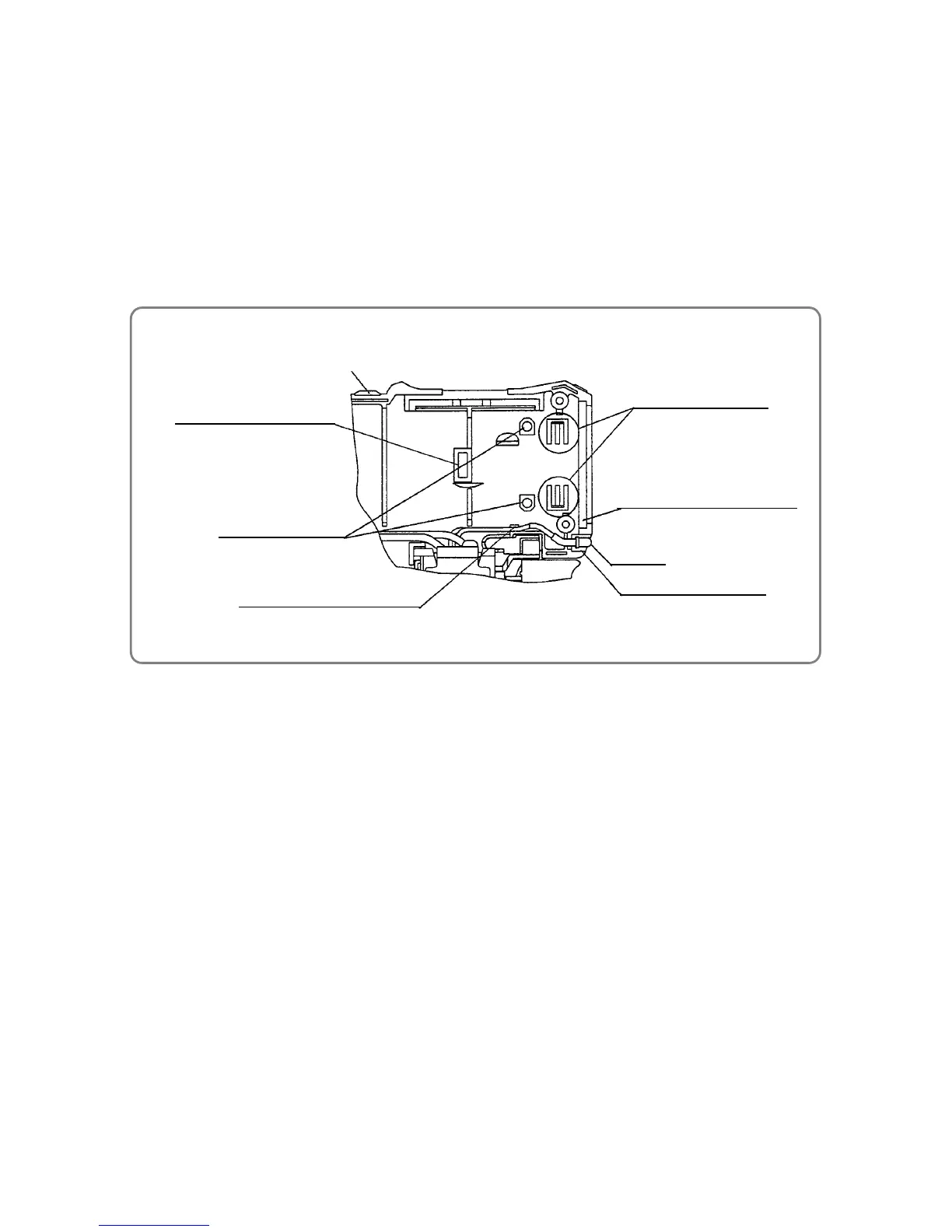
(1) Attach the LED to Housing (A). (B)Set [29]. When attaching the LED, be careful to prevent not to twist
the LED wire (delivered as an accessory for DC-Speed Control Switch [35]). Also be sure to run the LED
wire through the fixing rib on the housing. (See the figure below.)
(2) Motor DC12V [28] and Gear Box Ass’y [3] (already coupled) and Shift Knob [33] in Housing (A). (B)Set [29].
When mounting these parts, the convex features of Gear Case [9] and Motor Spacer [27] must be fitted
into the corresponding concave features of Housing (A). (B)Set [29]; the convex feature of Clutch Dial [4]
must be fitted into the corresponding concave feature of Housing (A). (B)Set [29]. Also, the two Needles [16]
projecting from Gear Case [9] must be fitted into the two holes on Housing (A). (B)Set [29]. Be careful to
prevent the LED wire from being caught between the housing and mounted parts. (See the figure below.)
Housing (A). (B)Set [29] (A)
Part to mount
Motor Spacer [27]
Parts to mount
Needles [16]
LED
LED mounting space
Parts to mount
Gear Case [9]
Rib to fix the LED wire
Part to mount Clutch Dial [4]
 Loading...