--- 15 ---
(d) Install the Shift Arm [22] into the assembly reassembled in step (c).
With the ridge at the Shift Arm [22] facing the Motor [31] side, first install them on the unmarked side of the
assembly reassembled in step (c). Then insert the projections on the Shift Arm [22] into the holes in the
Rear Case [20] and make sure that the projections are fitted into the grooves in the Slide Ring Gear [23]
mounted within the Rear Case [20]. (See Fig. 12.)
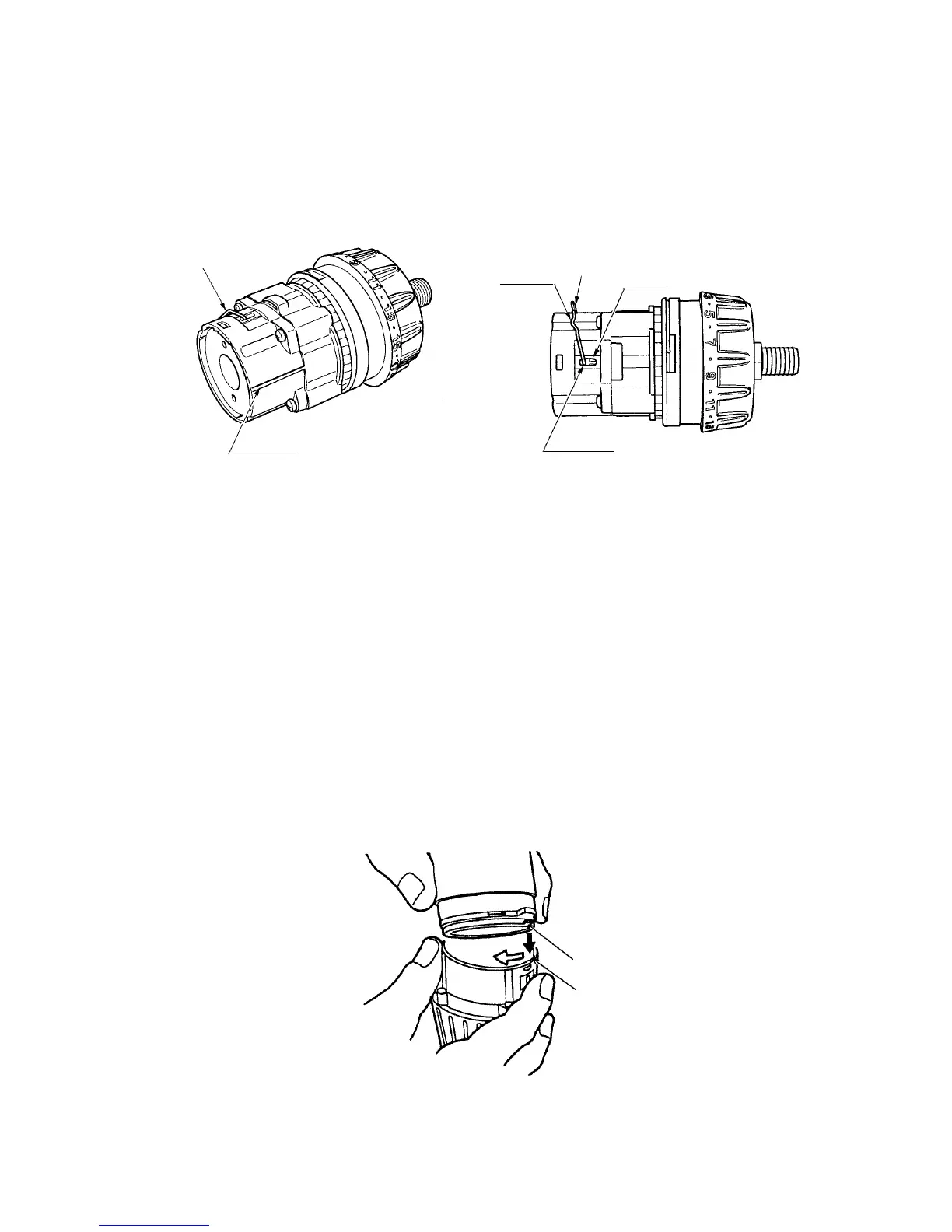
Fig. 12
[22]
Ridge
[22]
Hole
Groove
Mark
(e) Install the Drill Chuck 13VLRF-N (W/O Chuck Wrench) [2].
Install the Drill Chuck 13VLRF-N (W/O Chuck Wrench) [2] using the Wrench 14 mm (special repair tool,
Code No. 873929) and secure it with the Special Screw (Left Hand) M6 x 23 [1].
(f) Install the Shift Knob [41] into the assembly reassembled in step (e).
When installing the Shift Knob [41] into the Shift Arm [22], note that the "LOW" mark on the Shift Knob [41]
faces the Motor [31] with the Shift Arm [22] engaged with the recess in the Shift Knob [41].
(g)
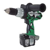
Install the assembly reassembled in step (1) and the assembly reassembled in step (f) together. (See Fig. 13.)
Fit the projection on the Motor Spacer [30] into the recess in the Rear Case [20] while ensuring that the
Shift Knob [41] is aligned with the positive side of the Motor [31] and turn the Motor Spacer [30] clockwise
when viewed from the rear of the Motor [31] until it can turn no further. During installation, make sure that
the pinion press-fitted onto the shaft of the Motor [31] and Planet Gear (A) Set (3 pcs.) [27] mesh properly.
Fig. 13
Projection
Recess