Chapter 7 Explanation of Functions
7 - 16
7.4 Using the analog terminal
7.4.1 Analog input (O/OI)
This inverter has an external analog input terminal.
If you want to switch the voltage and current inputs, use the switch on the board(SW6).
Voltage input : 0 to 10V (Variable resistor is a voltage input.)
Current input : 0 to 20mA (Please set the case of “4 to 20mA”to “A013=20%”)
The analog input signal can be assigned the following functions.
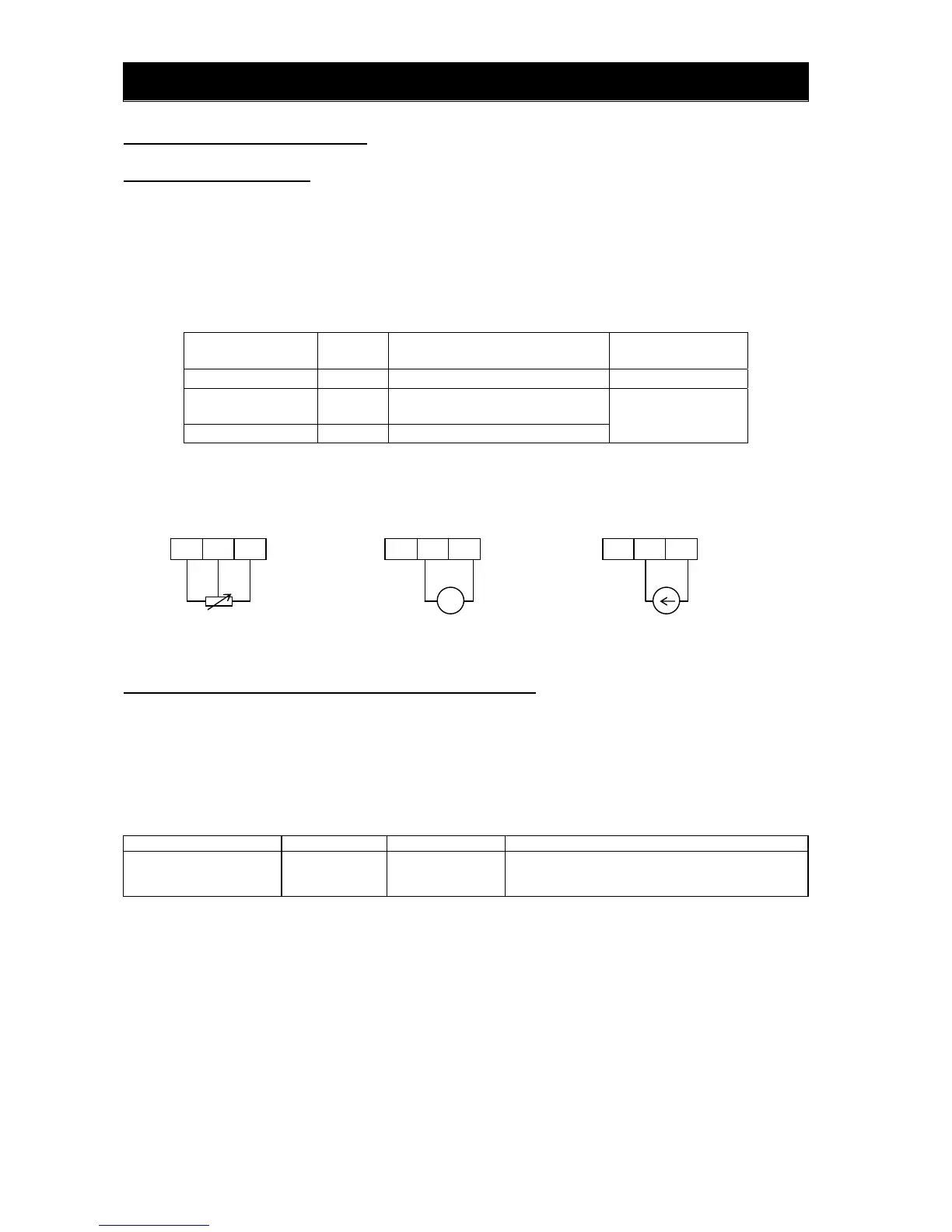
Item
Function
code
Data Description
Frequency command A001 01 01:O/OI input
PID enable A071
01(PID Enable)
02(PID Enable with reverse output)
PV source A076 01(O/OI)
Example of wiring
Please refer to section 3.2 about SW6 setting.
7.4.2 External analog input (O/OI) filter setting [A016]
The external analog input filter setting function allows you to set the input-voltage/input-current sampling
time to be applied when frequency commands are input as external analog signals.
You can use this filter function effectively for removing noise from the frequency-setting circuit signal.
If the noise disables the stable operation of the inverter, increase the setting. Setting a larger value makes
the inverter response slower. The filtering constant is "set value (1 to 30) x 2 ms."
When the setting is "31" (factory setting), a hysteresis of ±0.1 Hz is added to the filtering constant (500
ms).
Item Function code Range of data Description
External frequency filter
time const.
A016 1. to 30. or 31.
Setting of 1. to 30.: "Set value x 2" ms filte
 Loading...