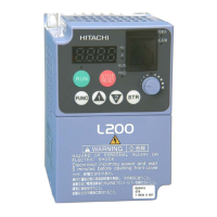
Do you have a question about the Hitachi L200 Series and is the answer not in the manual?
Describes safety instructions, signal words, and symbols used in the manual.
Details precautions for working with high voltage to prevent electric shock.
General safety guidelines for installation, operation, and maintenance.
Continues general safety guidelines, grounding, and wiring.
Lists specific cautions for mounting and orientation.
Lists warnings related to electrical practices and wire specifications.
Details cautions for electrical practices and wire specifications.
Lists cautions related to powerup testing procedures.
Lists warnings about configuring drive parameters.
Lists warnings for operating and monitoring the inverter.
Continues warnings for operations and monitoring.
Lists cautions for operations and monitoring.
Lists warnings and cautions for troubleshooting and maintenance.
Provides general warnings and cautions.
Cautions regarding stopping operation and wiring practices.
Summarizes UL guidelines for installation and wiring.
Lists warnings related to wiring practices and wire sizing for UL compliance.
Specifies UL listed circuit breakers and fuse sizes for input power.
Explains Hitachi L200's solid-state motor overload protection.
Provides model-specific specifications for 200V class inverters.
Provides specifications for 400V class inverters.
Continues specifications for 200V class models.
Continues specifications for 400V class models.
Details how to connect the inverter output to the motor and grounding.
Provides a step-by-step guide for installing the inverter.
Lists cautions and guidelines for selecting a suitable mounting location.
Emphasizes the importance of proper ventilation and clearance.
Lists important cautions and warnings before starting wiring.
Provides a table to determine appropriate wire and fuse sizes based on motor output.
Guides on connecting the inverter's power input to the supply.
Details on connecting the inverter output to the motor and grounding.
Outlines the procedure for conducting a powerup test.
Lists precautions for the powerup test and general operation.
Provides a visual map of navigating parameters and functions using the keypad.
Guides on configuring necessary parameters for motor startup.
Instructions for setting the motor's base frequency and associated cautions.
Guides on configuring the inverter's thermal overload protection based on motor current.
A checklist and steps to run the motor after parameter setup.
Lists parameters for monitoring system values like output frequency and current.
Details how to monitor trip events, history, and related information.
Defines the basic frequency (speed) profile using parameters like frequency, acceleration, and deceleration.
Explains how to select sources for output frequency and run commands.
Covers fundamental settings affecting inverter output, like base and maximum frequency.
Details the configuration of DC braking for enhanced stopping torque.
Explains the PID loop for controlling process variables and its parameters.
Explains how the inverter resumes operation after a fault.
Details thermal overload protection settings for the inverter and motor.
Continues discussion on electronic thermal overload settings.
Describes the software lock function for preventing accidental parameter changes.
Details function codes and options for configuring input terminals.
Lists parameters for configuring the inverter's serial communications port.
Details parameters for configuring motor characteristics.
Lists caution messages related to operating procedures.
Lists warning messages related to operating procedures.
Introduces programmable inputs, sinking/sourcing options, and DIP switch configuration.
Describes storing and accessing up to 16 target frequencies using intelligent terminals.
Describes using the [DB] terminal to enable DC braking and related parameters.
Describes how the [EXT] terminal triggers a trip event and stops the inverter.
Explains the USP function to prevent automatic startup without intervention.
Describes how the [SFT] terminal locks parameters from editing.
Details how the [RS] terminal clears trip states and resets the inverter.
Explains how to protect motors from overheating using a thermistor and terminal [TH].
Explains the [AL] signal and relay contacts for fault conditions.
Explains how the PID loop calculates ideal output frequency and requires sensor wiring.
Explains the purpose of dynamic braking for improving motor stopping ability.
Lists essential safety messages before troubleshooting or maintenance.
Addresses probable causes and solutions when the motor will not run or supply voltage.
Covers issues like reversed motor direction and heavy load conditions.
Explains how the inverter detects and records fault conditions.
Continues the list of error codes and their causes.
Lists common error codes and their associated causes.
Explains how to access and review trip history data via the monitor menu.
Provides a step-by-step guide to restore inverter parameters to factory defaults.
A chart detailing inspection items, check criteria, and cycles.
Guides on connecting the inverter to a ModBus network via serial port and cable wiring.
Lists ModBus-related parameters and their required settings for communication.
Lists holding registers for 'D' Group monitor functions, including trip data.
Continues listing holding registers for 'D' Group monitor functions.
Lists holding registers for 'F' Group parameters like frequency and acceleration.
Continues listing holding registers for 'F' Group parameters.
Lists holding registers for 'A' Group standard functions like source selection and frequency settings.
Continues listing holding registers for 'A' Group functions, including analog input settings.
Lists holding registers for 'B' Group functions like restart modes and thermal settings.
Continues listing holding registers for 'B' Group functions, including over-voltage LADSTOP and carrier mode.
Lists holding registers for 'C' Group functions like terminal configuration and overload level.
Continues listing holding registers for 'C' Group functions, including delay functions.
Lists holding registers for 'H' Group motor constants like capacity and poles.
Lists default settings for 'A' Group standard functions.
Continues listing default settings for 'A' Group standard functions.
Lists default settings for 'B' Group fine-tuning functions.
Continues listing default settings for 'B' Group fine-tuning functions.
Lists default settings for 'C' Group intelligent terminal functions.
Continues listing default settings for 'C' Group intelligent terminal functions.
Lists default settings for 'H' Group motor constants.
Provides guidelines for satisfying EMC directive requirements in EU countries.
Provides a checklist for ensuring inverter operates within proper EMC conditions.
| Output Frequency | 0.1-400Hz |
|---|---|
| Communication | RS-485 (Modbus RTU) |
| Frequency Range | 0.1-400Hz |
| Operating Temperature | -10°C to +50°C |
| Storage Temperature | -20°C to +65°C |
| Input Voltage | 200-240V |
| Control Method | V/f control, Sensorless vector control |
| Overload Capacity | 150% for 60 seconds |
| Protection | Overcurrent, overvoltage, undervoltage, overload, overheating, short circuit |
| Output Voltage | 3-phase, 0 to input voltage |
| Cooling Method | Forced air cooling |
| Humidity | 5% to 95% RH (non-condensing) |
| Altitude | Up to 1000m without derating |
| Braking Unit | Built-in braking transistor (for models up to 7.5kW), External braking resistor can be connected |




 Loading...