Do you have a question about the Hitachi LH1 Series and is the answer not in the manual?
Overview of the LH1 Series Inverter Basic Guide.
Main subject of the document.
Important warnings and precautions for using the inverter.
How to inquire about product issues and warranty details.
Details on receiving warranty service for the inverter.
Precautions to consider when applying the inverter.
Contact details for Hitachi support.
Classification of safety warnings (DANGER, WARNING, CAUTION).
Explanation of safety symbols used in the manual.
General cautions for handling the inverter.
Safety measures during inverter installation.
Safety measures during inverter wiring.
Safety precautions for starting and testing the inverter.
Safety measures for maintenance and inspection.
Safety guidelines for inverter disposal.
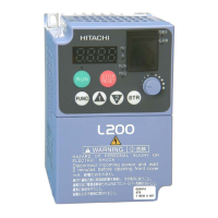
Verifying the inverter contents and model.
Guidelines for physically installing the inverter.
Recommended environmental conditions for installation.
Proper methods and positions for mounting the inverter.
Physical dimensions and mounting hole details of the inverter.
Wiring diagrams and peripheral equipment connections.
Instructions for wiring the main power circuit.
Guidance on selecting appropriate wires and terminals.
Selection of suitable circuit breakers and contactors.
Information on using chopper braking resistors.
Terminal wiring diagrams for various models.
Wiring for the control circuit and switch settings.
Details on input terminals and their default functions.
Details on output terminals and their default functions.
Wiring and configuration for analog input/output.
Wiring for the external thermistor sensor.
Wiring for FM output terminals.
Wiring for serial communication (Modbus).
Wiring for 24V power supply connections.
Identification of residual risks after installation.
Setting motor parameters for induction and synchronous motors.
Setting frequency source via keypad.
Setting run command source via keypad.
Using multispeed terminals for frequency command.
Operating using FW/RV terminals for run command.
Potentiometer frequency command setup.
Operating using 3WIRE terminals for run command.
Adjusting analog input terminals (Ai1/Ai2).
Adjusting analog output terminals (Ao1/Ao2/FM).
Adjusting analog input terminal (Ai3).
Preventing input terminal malfunction.
Stabilizing an output terminal.
Overview of the digital operator keypad components and functions.
Understanding the code display system on the monitor.
Navigating through monitored data displays.
Step-by-step guide for specifying codes and data.
Installing the digital operator onto the inverter or control cabinet.
Understanding parameter naming conventions.
Detailed explanations of monitor functions.
Explaining parameter naming conventions.
Understanding parameter grouping and ordering.
Detailed explanation of parameters.
List of functions assignable to input terminals.
Settings for pulse train input counters.
Adjusting analog input parameters.
Settings for thermistor error detection.
Adjusting parameters for MOP/VR input.
Configuring intelligent output terminals.
Stabilizing output terminals with delay times.
List of functions for output terminals.
Configuring logic output terminals with calculation selection.
Adjusting analog output parameters.
Settings for low-current detection signals.
Settings for overload detection signals.
Setting frequency arrival signals.
Settings for over-torque signals.
Settings for electronic thermal warnings.
Setting for 0Hz speed detection.
Settings for cooling fin overheat warnings.
Warning settings for accumulated run/power-on times.
Window comparator settings for detecting terminal disconnection.
Configuration for Modbus communication.
Settings for EzCOM peer-to-peer communication.
Configuration for USB node settings.
Parameters for auto-tuning the motor.
Adjusting stabilization constant for hunting.
Adjusting speed response gain for motor control.
Settings for ASR gain switching modes.
Core parameters for induction motors.
Motor constants for induction motors.
Setting the minimum operating frequency.
Adjusting manual torque boost settings.
Enabling and configuring the Eco Drive function.
Configuring Free V/f settings.
Adjusting slip compensation for V/f feedback control.
Adjusting output voltage gain.
Adjusting automatic torque boost parameters.
Parameters for starting vector control.
Adjusting gains for motor control.
Core parameters for permanent magnet synchronous motors.
Configuring PROFINET communication.
Configuring DeviceNet communication.
Handling errors with optional cassettes.
Configuring P1-FB Encoder feedback.
Settings for pulse train input terminals on P1-FB.
Operating the P1-FS Functional Safety Option.
Adjusting analog input parameters for P1-AG option.
Configuring window comparator outputs.
Adjusting analog output parameters for P1-AG option.
Configuring Ethernet communication options.
Interface settings for communication options.
Ethernet communication settings for Group 1.
Ethernet communication settings for Group 2.
Configuring emergency-force drive mode settings.
Settings for simulation mode.
Setting and managing passwords for security.
Configuring keypad display modes.
Adjusting and clearing accumulated power display.
Settings for software lock operations.
Restricting keypad copy functions.
Settings for keypad low battery warnings.
Actions to take when keypad communication is lost.
Selecting display for 2nd motor and option parameters.
Enabling user-parameter auto-setting.
Settings for MOP/VR keypad operations.
Procedures for initializing the inverter.
Configuring and using the trace function.
Settings for EzSQ program operation.
Descriptions of basic errors and corrective actions.
Common errors, estimated causes, and corrective actions.
General notes for inspection and maintenance.
Daily checks to perform while the inverter is operating.
Instructions for cleaning the inverter.
Periodic checks to perform when the inverter is stopped.
Detailed schedule and methods for daily and periodic inspections.
Procedure for testing insulation resistance.
Warning against performing dielectric withstand tests.
Method for checking inverter/converter circuits with a multimeter.
Curve showing smoothing capacitor life based on ambient temperature.
Explanation of lifespan alarm outputs.
Detailed specifications for 400V class models.
General specifications applicable to all models.
Derating curves for output current based on carrier frequency.
| Series | LH1 |
|---|---|
| Cooling Method | Forced air cooling |
| Enclosure Rating | IP20 |
| Type | Inverter |
| Protection Functions | Overcurrent, Overvoltage, Undervoltage, Overheat, Short Circuit |
| Output Power Range | 0.4 - 15 kW |
| Operating Temperature | -10°C to +50°C |
| Storage Temperature | -20°C to +60°C |
| Humidity | 5 to 95% RH (non-condensing) |
| Altitude | Up to 1000m |




 Loading...