2-1
Chapter 2
Installation and Wiring
2.1 Check the Inverter
Check the contents in the package, and confirm the
inverter model with a specification label.
The model of the product is as follows:
E.g.: 400V class input voltage for China
Applicable motor capacity is 7.5kW
rated current 17.0A
(1) Series name LH1
(2) Motor Capacity
075 means 0.75kW
(3) Input power specification
H: three-phase 400V class
(4) Panel
F: panel (MOP)equipped
(5) Region (None): Japan;
C: China/Southeast Aisa
• Specification label example
Description example for LH1-075HFC
(*) means eigenvalues
Configuration and description contents vary
depending on the model.
Contact to your supplier or local Hitachi distributor
or service station for more details.
If the inverter is shipped incorporated with optional
products, optional instruction will be enclosed.
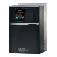
LH1-075HFC example illustration in below.
ratings
(Frequency/voltage/No. of
phases/Rate current)
MFG No.; factory serial No.
Input ratings
(Frequency/voltage/No.of
phases/Current)
Basic Guide
(This document)
Eye bolts for hanging the inverter
LH1-450HFC~LH1-750HFC
Control circuit
terminal block
Optional slots
Refer to each optional product
instruction for detail.
 Loading...
