L200 Inverter
iii
WARNING: Rotating shafts and above-ground electrical potentials can be hazardous.
Therefore, it is strongly recommended that all electrical work conform to the National
Electrical Codes and local regulations. Installation, alignment and maintenance should
be performed only by qualified personnel.
Factory-recommended test procedures included in the instruction manual should be
followed. Always disconnect electrical power before working on the unit.
CAUTION:
a) Class I motor must be connected to earth ground via low resistive path (< 0.1Ω)
b) Any motor used must be of a suitable rating.
c) Motors may have hazardous moving parts. In this event suitable protection must
be provided.
CAUTION: Alarm connection may contain hazardous live voltage even when inverter is
disconnected. When removing the front cover for maintenance or inspection, confirm
that incoming power for alarm connection is completely disconnected.
CAUTION: Hazardous (main) terminals for any interconnection (motor, contact
breaker, filter, etc.) must be inaccessible in the final installation.
CAUTION: This equipment should be installed in IP54 or equivalent (see EN60529)
enclosure. The end application must be in accordance with BS EN60204-1. Refer to the
section “
Choosing a Mounting Location” on page 2–9. The diagram dimensions are to
be suitably amended for your application.
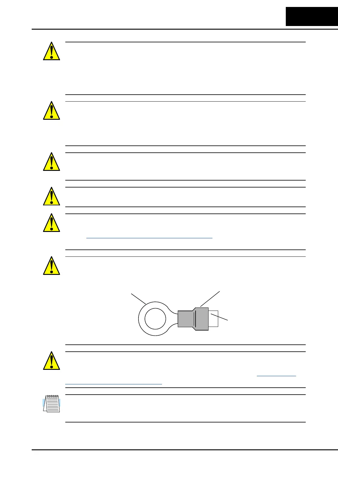
CAUTION: Connection to field wiring terminals must be reliably fixed having two
independent means of mechanical support. Use a termination with cable support (figure
below), or strain relief, cable clamp, etc.
CAUTION: A double-pole disconnection device must be fitted to the incoming main
power supply close to the inverter. Additionally, a protection device meeting IEC947-1/
IEC947-3 must be fitted at this point (protection device data shown in “
Determining
Wire and Fuse Sizes” on page 2–16).
NOTE: The above instructions, together with any other requirements highlighted in this
manual, must be followed for continued LVD (European Low Voltage Directive)
compliance.
Terminal (ring lug) Cable support
Cable

 Loading...


