English
19
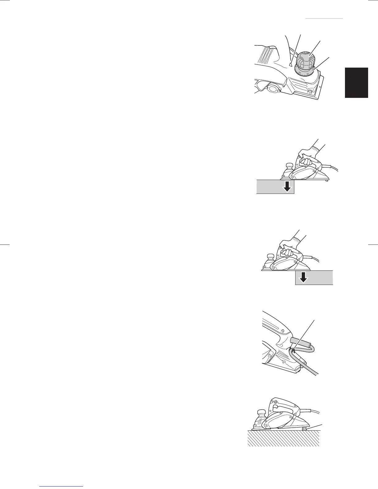
2. Adjusting the cutter depth
(1) Turn the knob in the direction indicated by the arrow in
Fig. 5 (clockwise), until the triangular mark is aligned with
the desired cutting depth on the scale. The scale unit is
graduated in millimeters.
(2) The cutting depth can be adjusted within a range of
0
-
2.6 mm.
3. Surface cutting
Rough cutting should be accomplished at large cutting
depths and at a suitable speed so that shavings are
smoothly ejected from the machine. To ensure a smoothly
fi nished surface, fi nish cutting should be accomplished at
small cutting depths and at low feeding speed.
4. Beginning and ending the cutting operation
As shown in Fig. 6, place the front base of the planer on
the material and support the planer horizontally. Turn ON
the power switch, and slowly operate the planer toward the
leading edge of the material. Firmly depress the front half
of the planer at the fi rst stage of cutting, as shown in Fig. 7,
depress the rear half of the planer at the end of the cutting
operation. The planer must always be kept fl at throughout the
entire cutting operation.
5. Precaution after fi nishing the planing operation
When the planer is suspended with one hand after fi nishing the
planing operation, ensure that the cutting blades (base) of the
planer do not contact or come too near your body. Failure to do
so could result in serious injury.
6. Cord holder (Fig. 8)
A cord holder is provided on the back of the handle below
where the cord is attached. Clip the cord in the holder from
right or left depending on which side you want the cord to be.
7. Stand (Fig. 9)
Lift the back of the planer to extend the foot from the base.
Having the stand extended when you put the planer down
prevents contact between the blade and the material.
Mark
Knob
Scale
Fig. 5
Fig. 6
Beginning of cutting operation
Fig. 7
End of cutting operation
Cord holder
Fig. 8
Stand
Fig. 9
000BookP20SFChS.indb19000BookP20SFChS.indb19 2016/07/1913:40:452016/07/1913:40:45

 Loading...