English
22
BLADE ASSEMBLY AND DISASSEMBLY AND
ADJUSTMENT OF BLADE HEIGHT
(FOR RESHARPENABLE BLADE TYPE)
1. Blade disassembly
(1) As shown in Fig. 15 on page 21, use the
accessory box wrench to loosen the three bolts
used to retain the blade, and remove the blade
holder.
(2) As shown in Fig. 16 on page 21, slide the blade in
the direction indicated by the arrow to disassemble
the blade.
CAUTION
Be careful not to injure your hands.
2. Blade assembly
CAUTION
Prior to assembly, thoroughly wipe off all
swarf accumulated on the blade.
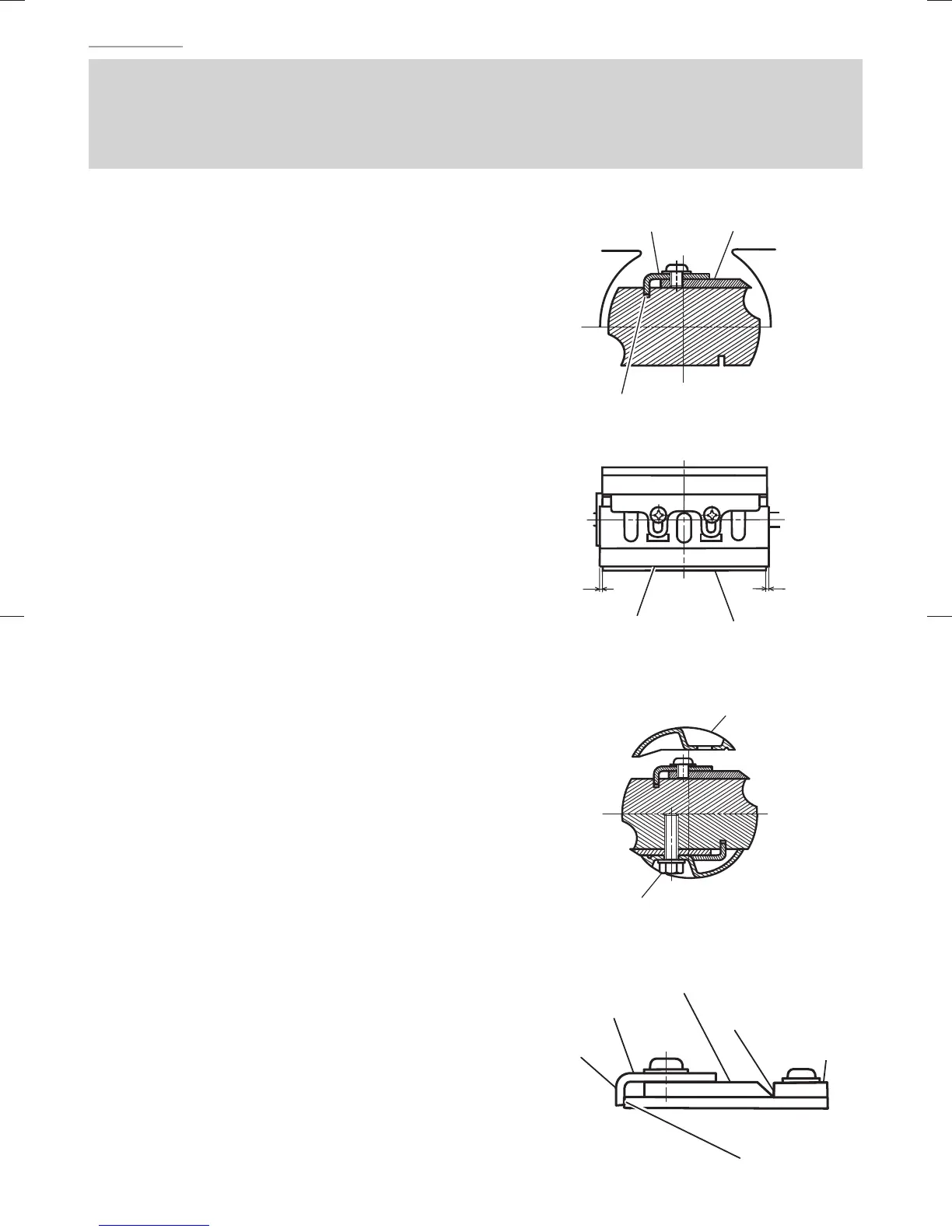
(1) Insert a turned portion of set plate (A) attached
to the blade into a groove on the fl at portion of
the cutter block. (Fig. 19 on page 21 and
Fig. 22)
Set the blade so that both sides of the blade
protrude from the width of the cutter block by about
1 mm (Fig. 23)
(2) Place the blade holder on the completed assembly,
as shown in Fig. 24, and fasten it with the three
bolts. Ensure that the bolts are securely tightened.
(3) Turn the cutter block over, and set the opposite side
in the same manner.
3. Adjustment of blade height
(1) Loosen the 2 screws holding on the blade and set
plate (A).
(2) Press the turned surface of set plate (A)
to the wall surface b while adjusting the
blade edge to the wall surface a of the set
gauge. Then, tighten them with the
2 screws. (Fig. 17 on page 21 and
Fig. 25)
Set plate (A)
Blade (Resharpnable
blade type)
Fig. 22
Groove
1 mm1 mm
Blade (Resharpnable
blade type)
Cutter block
Fig. 23
Blade holder
Bolt
Fig. 24
Turned surface
Set plate (A)
Blade (Resharpnable blade type)
Wall surface a
Set gauge
Wall surface b
Fig. 25
000BookP20SFChS.indb22000BookP20SFChS.indb22 2016/07/1913:40:452016/07/1913:40:45
 Loading...