English
21
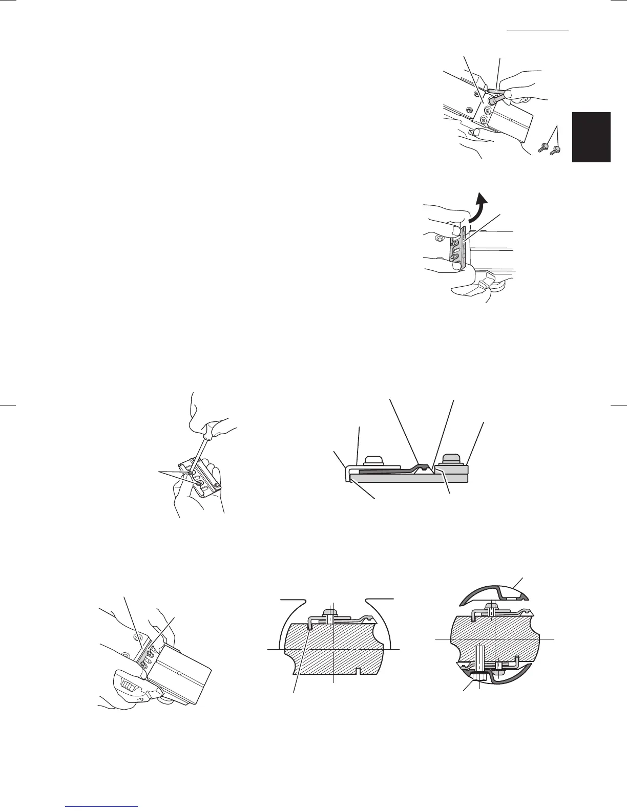
(1) As shown in Fig. 15, use the box wrench to loosen the
three bolts used to retain the carbide blade, and remove
the blade holder.
(2) As shown in Fig. 16, after removing the carbide blade,
slide set plate (B) in the direction indicated by the arrow to
disassemble set plate (B).
(3) Loosen the 2 screws holding on the carbide blade and set
plate (A), set plate (B).
(4) As shown in Fig. 17, 18, press the turned surface of set
plate (A) to the wall surface b while adjusting the carbide
blade edge to the wall surface a of the set gauge. Then,
tighten them with the 2 screws.
(5) As shown in Fig. 19, 20, insert a turned portion of set plate
(A) attached to set plate (B) into a groove on the fl at portion
of the cutter block.
(6) As shown in Fig. 21, place the blade holder on the
completed assembly and fasten it with the three bolts.
Ensure that the bolts are securely tightened. Follow the
same procedures for the opposite side carbide blade.
Blade holder
Box wrench
Bolt
Fig. 15
Set plate (B)
Fig. 16
Machine
screw
Fig. 17
Flat portion of the cutter block
Set plate (A)
Fig. 19
Groove
Fig. 20
Blade holder
Bolt
Fig. 21
Turned surface
Set plate (A)
Set plate (B)
Carbide blade
(Double edged blade type)
Set gauge
Wall surface b
Wall surface a
Fig. 18
000BookP20SFChS.indb21000BookP20SFChS.indb21 2016/07/1913:40:452016/07/1913:40:45
 Loading...