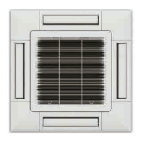
6.5 ATTACHMENT OF CORNER COVER WITH MOTION SENSOR AND RADIATION SENSOR
ON THE AIR PANEL MODEL P-AP160NAE2
? NOTE
• Pay attention that the detecting function will be decreased if the lens
for motion sensor smudges.
• In this case, wipe off smudges by a cotton swab soaked alcohol
(Isopropyl alcohol is recommended) or a soft cloth.
• When wiping off smudges on the lens for motion sensor, do not apply
excessive force.
• If excessive force is applied, the resin lens may be damaged so that
may cause malfunctions such as misdetection or undetectable of the
motion.
a. The corner cover with sensor can be attached to any of
corners (three directions, Ⓐ , Ⓑ and Ⓓ). Determine the
best location in line with user's requirements.
? NOTE
• The corner cover encasing the Motion Sensor should be placed in the
corner closest to the wired controller.
• Do not attach at location Ⓒ.
• When the Motion Sensor is attached at location Ⓐ, control setting on
the wired controller is not necessary.
Removed form of
Corner Cover with Sensor
Attachment Position
Stamp (A~D)
A
BC
D
Air Panel
Refrigerant Pipe
Connections
Do not
attach here.
b. Remove the electrical box cover and connect the
connecting cable (attached inside the air panel) at CN33
in the electrical box.
CN33
? NOTE
• In the RCI-FSR1 4-way cassette indoor unit where the PCB number
PI1942 is mounted, a patch cord inserted into the CN33 connector is
supplied. This patch cord will be used to connect the motion sensor
of the panel P-AP160NAE2 to the indoor unit PCB.
• The CN10 connector is only available for connection of the Motion
Sensor kit SOR-MSK and for panels P-N23NA2, and P-AP160KA3.
c. Run the connecting cable from CN33 to the corner cover
with motion sensor through top of the mounting plate.
Then measure the distance 100mm to 200mm from the
corner cover to the relay connector as shown below.
100~200mm
Connecting Cable
Relay Connector
Mounting
Plate
Indoor Unit
Wiring Connection
d. Clamp the extra length of the relay wire by the plastic
band and store it at inside the ceiling.
e. Access the connecting cable from the corner of the air
panel. Then connect the wiring for the sensor to the
relay connector. After making the connection, cover the
relay with the wiring cover and install the cable bands as
shown in the diagram below.
INSTALLATION
PMML0569 rev.2 - 07/20236

 Loading...

