EasyManua.ls Logo

Hitachi RAS-10XH1 User Manual

Hitachi RAS-10XH1
133 pages
To Next Page IconTo Next Page
Page #1 background imageLoading...
Page #1 background image
TC
SERVICE MANUAL
TECHNICAL INFORMATION
REFER TO THE FOUNDATION MANUAL
ROOM AIR CONDITIONER
SPECIFICATIONS AND PARTS ARE SUBJECT TO CHANGE FOR IMPROVEMENT
FOR SERVICE PERSONNEL ONLY
NO. 0792E
RAS-10XH1 / RAC-10XH1
RAS-14XH1 / RAC-14XH1
798
295
233
11.5
750 (+86)
570
288 (+56)
36
RAS-10XH1 RAC-10XH1
1ø, 220V - 230V, 50Hz
465 (70 - 960)
2.49 - 2.38
2.5 (0.5 - 3.4)
8,533 (1,707 - 11,604)
585 (65 -1,410)
3.13 - 2.99
3.2 (0.6 - 5.8)
10,922 (2,048 - 19,795)
798
295
233
11.5
750 (+86)
570
288 (+56)
36
RAS-14XH1 RAC-14XH1
1ø, 220V - 230V, 50Hz
835 (70 - 1,350)
4.47 - 4.27
3.5 (0.5 - 4.1)
11,946 (1,707 - 13,993)
875 (65 -1,490)
4.68 - 4.48
4.2 (0.5 - 6.1)
14,335 (1,707 - 20,819)
SPECIFICATIONS
SPECIFICATIONS‥‥‥‥‥‥‥‥‥‥‥‥‥‥‥‥‥‥‥
HOW TO USE‥‥‥‥‥‥‥‥‥‥‥‥‥‥‥‥‥‥‥‥
CONSTRUCTION AND DIMENSIONAL DIAGRAM‥‥‥‥
MAIN PARTS COMPONENT‥‥‥‥‥‥‥‥‥‥‥‥‥‥
WIRING DIAGRAM‥‥‥‥‥‥‥‥‥‥‥‥‥‥‥‥‥‥
WIRING DIAGRAM OF THE PRINTED WIRING BOARD
‥‥‥
BLOCK DIAGRAM‥‥‥‥‥‥‥‥‥‥‥‥‥‥‥‥‥‥
BASIC MODE‥‥‥‥‥‥‥‥‥‥‥‥‥‥‥‥‥‥‥‥
REFRIGERATING CYCLE DIAGRAM ‥‥‥‥‥‥‥‥‥
DISASSEMBLY&ASSEMBLYPROCEDURE‥‥‥‥‥‥
DESCRIPTION OF MAIN CIRCUIT OPERATION‥‥‥‥
SERVICE CALL Q&A ‥‥‥‥‥‥‥‥‥‥‥‥‥‥‥‥
TROUBLE SHOOTING‥‥‥‥‥‥‥‥‥‥‥‥‥‥‥‥
PARTS LIST AND DIAGRAM‥‥‥‥‥‥‥‥‥‥‥‥‥
CONTENTS
INDOOR UNIT + OUTDOOR UNIT
DECEMBER 2008 Hitachi Appliances, Inc.
4
5
30
32
35
37
43
45
78
79
82
102
110
143
After installation
DC INVERTER
COOLING
HEATING
TYPE
MODEL
POWER SOURCE
TOTAL INPUT
TOTAL AMPERES
CAPACITY
TOTAL INPUT
TOTAL AMPERES
CAPACITY
DIMENSIONS
NET WEIGHT
(mm)
(A)
(B.T.U./h)
W
H
D
(kg)
(kW)
(A)
(B.T.U./h)
(kW)
(W)
(W)
INDOOR UNIT
OUTDOOR UNIT
INDOOR UNIT
OUTDOOR UNIT
OUTDOOR UNIT
INDOOR UNIT
RAS-10XH1
RAS-14XH1
RAC-10XH1
RAC-14XH1
Question and Answer IconNeed help?

Do you have a question about the Hitachi RAS-10XH1 and is the answer not in the manual?

Hitachi RAS-10XH1 Specifications

General IconGeneral
TypeSplit System
Heating Capacity3.2 kW
Power Supply220-240V, 50Hz
RefrigerantR410A
Indoor Unit Weight9 kg

Summary

SERVICE MANUAL TECHNICAL INFORMATION

SPECIFICATIONS

SAFETY DURING REPAIR WORK

WORKING STANDARDS FOR PREVENTING BREAKAGE OF SEMICONDUCTORS

CAUTION

SPECIFICATIONS

HOW TO USE

PRECAUTIONS DURING OPERATION

Critical safety measures to observe while the unit is running.

PRECAUTIONS DURING INSTALLATION

Important steps and safety warnings for installing the air conditioner unit.

PRECAUTIONS DURING SHIFTING OR MAINTENANCE

Safety guidelines for moving or maintaining the air conditioner unit.

NAMES AND FUNCTIONS OF EACH PART

INDOOR UNIT

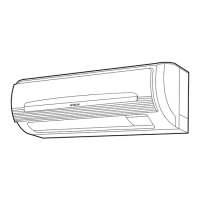
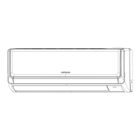
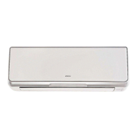
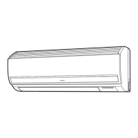
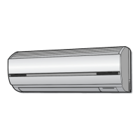
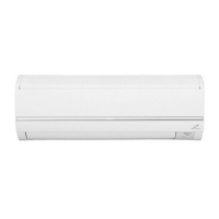
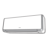
Description of parts and their functions within the indoor unit.

OUTDOOR UNIT

Description of components and their functions within the outdoor unit.

INDOOR UNIT CONTROL PANEL / CLEANING UNIT

Details of the indoor unit's control panel and cleaning unit components.

REMOTE CONTROLLER

NAMES AND FUNCTIONS OF EACH PART (continued)

Continuation of the remote controller's parts and their functions.

INSTALLING ANTI-MOLD WASABI CASSETTE

FILTER CLEANING UNIT OPERATION CHECK

PREPARE THE REMOTE CONTROLLER

PREPARE THE REMOTE CONTROLLER (continued)

AUTOMATIC OPERATION

MANUAL OPERATION (HEATING, DEHUMIDIFYING, COOLING, DRY COOL)

HEATING OPERATION

Steps to operate the air conditioner in heating mode.

DEHUMIDIFYING OPERATION

Steps to operate the air conditioner in dehumidifying mode.

DEHUMIDIFYING OPERATION (continued)

COOLING OPERATION

DRY COOL OPERATION

IONIZED MIST OPERATION

STAINLESS PLASMA AIR PURIFYING (FAN) OPERATION

INTERNAL CLEANING OPERATION

SLEEP OPERATION

AIR QUALITY MONITOR OPERATION

MOLD MONITOR OPERATION

PREFERENCE (COOLER/WARMER) OPERATION

POWERFUL OPERATION

ADJUSTING THE VERTICAL AIRFLOW DIRECTION

ADJUSTING THE HORIZONTAL AIRFLOW DIRECTION

TIMER PRESET OPERATION

FURTHER CONVENIENT TIMER FUNCTION

SLEEP TIMER OPERATION

FILTER CLEANING OPERATION

FILTER CLEANING OPERATION (continued)

HOW TO PROHIBIT THE FILTER CLEANING OPERATION

Procedure to disable the automatic filter cleaning operation.

MAINTENANCE

Maintenance of dust box

Instructions for cleaning and maintaining the dust box.

Maintenance of micro mesh stainless filter

Steps for removing, cleaning, and reinstalling the micro mesh stainless filter.

MAINTENANCE (continued)

Maintenance of micro mesh stainless filter (continued)

Continuation of steps for filter maintenance.

Maintenance of dust catcher

Procedure for removing and cleaning the dust catcher.

MAINTENANCE (continued)

Maintenance of filter cleaning wiper and wiper cover

Steps to clean the filter cleaning wiper and its cover.

UNDERSTANDING THE OPERATING MECHANISM

Movable panel

Description of the movable panel's function and operation.

Heating capability

Explanation of how the unit provides heating, especially in cold conditions.

Cooling, dehumidifying and dry cool capabilities

Explanation of the unit's capabilities in cooling, dehumidifying, and dry cool modes.

THE IDEAL WAYS OF OPERATION

TROUBLESHOOTING

FILTER CLEANING OPERATION

Troubleshooting steps for filter cleaning operation problems.

TROUBLESHOOTING (continued)

FILTER CLEANING OPERATION (continued)

Further troubleshooting for filter cleaning operations.

ANTI-MOLD WASABI CASSETTE

Information about the anti-mold wasabi cassette and potential issues.

PLEASE CHECK THE FOLLOWING BEFORE SERVICE

Essential pre-service checks for troubleshooting.

FAILURE OF IONIZED MIST GENERATOR AND ELECTRIC DUST COLLECTOR

Troubleshooting for failures of ion mist and electric dust collector.

THE FOLLOWING CASES DOES NOT INDICATE MALFUNCTION

TROUBLESHOOTING (continued)

TEMPORARY OPERATION

IF THE UNIT WOULD NOT BE USED FOR A LONG PERIOD OF TIME (MORE THAN 1 MONTH), PLEASE FOLLOW THE STEPS BELOW FOR MAINTENANCE

REGULAR INSPECTION

INSPECTION AND MAINTENANCE

Recommendations for inspection and maintenance beyond basic cleaning.

OPERATION DISPLAY CHART

CONSTRUCTION AND DIMENSIONAL DIAGRAM

OUTDOOR UNIT DIMENSIONAL DIAGRAM

MAIN PARTS COMPONENT

THERMOSTAT

Specifications and operation modes for the thermostat.

FAN MOTOR

Specifications and wiring details for the fan motor.

COMPRESSOR

WIRING DIAGRAM

WIRING DIAGRAM OF THE PRINTED WIRING BOARD

BLOCK DIAGRAM

BASIC MODE

Basic mode for cooling

Cooling, sleep

As-desired "powerful" operation

Basic mode for heating

Reversing valve defrost

Heating, sleep

Room low-temperature defrost

Dehumidification operation

Dehumidifying operation, sleep

Dry cool

Dry cool, sleep

Laundry

Dirt monitoring

Mold monitoring

Stainless steel plasma air purification operation

Ion mist operation

Internal cleaning

Pre-filter cleaning system operation control (1)

Pre-filter cleaning system operation control (2)

Pre-filter cleaning system operation control (3)

Operation diagram for filter cleaning (manual and forcible cleaning)

Operation diagram for filter cleaning 3 (timer stopped, servicing operation)

Operation diagram for filter cleaning 4 (remarks)

Operation diagram for filter cleaning (error detection 1)

Operation diagram for filter cleaning (error detection 2)

Operation diagram for filter cleaning (error detection 3)

Option selection

REFRIGERATING CYCLE DIAGRAM

DISASSEMBLY & ASSEMBLY PROCEDURE

3. Cleaning unit

4. Control P.W.B. components

5. Ion mist unit

6. Indicating P.W.B.

7. Dew pan components

8. Fan motor

1. Electrical installation

DESCRIPTION OF MAIN CIRCUIT OPERATION

1. Power relay operation

Details on how the power relay functions in the main circuit.

2. Control power circuit

3. Drive circuit of the indoor fan motor

4. Remote control reception circuit

5. Room temperature heat exchanger thermistor circuit

6. Humidity sensor circuit

Explanation of the humidity sensor circuit and its operation.

7. Indoor/outdoor communication circuits

8. Stepping motor drive circuit

9. Dirt sensor (gas sensor) circuit

10. Ion mist unit

11. Cleaner drive circuit

Cleaner

1. Power Circuit

(3) Smoothing capacitors ( C021, C022, 375μF, 420V )

(5) NF coils for C001, C002, C004, C005

(6) Surge absorber and varistors 1 and 2

2. Board-purpose power supply circuit

3. Latch-type reversing valve control circuit

4. Temperature detection circuit

5. Electrical expansion valve circuit

6. Control circuit of the DC fan motor

SERVICE CALL Q&A

Common, etc.

Wireless remote control

Changes in the time on the timer in quick dehumidification

Ion mist

Cleaner

TROUBLE SHOOTING

How to stop energizing the discharge procedure and power circuit

Other instructions

Troubleshooting support

Self-diagnosis display [Display on the indoor unit side]

Information on interpreting self-diagnosis displays on the indoor unit.

[Display on the outdoor unit side]

Information on interpreting self-diagnosis displays on the outdoor unit.

Self-diagnosis memory

How to access and interpret the stored self-diagnosis memory.

Self-diagnosis display function (indoor side display)

Self-diagnosis memory function

Operation with the forcible cooling switch

Running the indoor unit in isolation

Dividing the freezing cycle for the indoor electrical installation and the outdoor electrical installation

Checking the indoor unit electrical installation

1. Failure phenomenon: The power will not become turned on.

2.Failure phenomenon: The product will not receive a remote control signal.

How to identify sources of jamming in the reception of remote control signals

Effects of other electrical products

Sharing a grounding

Effects of radio waves

Effects of direct sunlight

3. Failure phenomenon: The compressor will not run.

4. Failure phenomenon: The fan motor will not stop.

5. Failure phenomenon: The clean lamp is blinking (on for 4 seconds, off for 1 second).

6. Failure phenomenon: The clean lamp is blinking (on for 1 second, dimmed for 1 second).

7. Failure phenomenon: The air purification lamp is blinking (on for 4 seconds, off for 1 second).

8. Timer lamp blinking: blinking once

9. Timer lamp blinking: blinking twice

10. Timer lamp blinking: blinking three times

11. Timer lamp blinking: blinking 5 times

12. Timer lamp blinking: blinking 9 times

13. Timer lamp blinking: blinking 10 times

14. Timer lamp blinking: blinking 12 times

15. Timer lamp blinking: blinking 13 times

Checking the electrical installation of the outdoor unit

Self-check

How to run the product with the outdoor unit test switch

HOW TO OPERATE THE OUTDOOR UNIT INDEPENDENTLY

Lighting mode of the self-diagnosis lamp

Lighting mode of the self-diagnosis lamp

CHECKING THE REMOTE CONTROLLER

INDOOR UNIT PARTS LIST AND DIAGRAM

MODEL RAS-10XH1, RAS-14XH1

Illustrated parts list and diagrams for the indoor unit components.

INDOOR UNIT PARTS LIST (continued)

OUTDOOR UNIT PARTS LIST

OUTDOOR UNIT EXPLODED VIEW DIAGRAM

OUTDOOR UNIT PARTS LIST (continued)

OUTDOOR UNIT PARTS LIST (continued)

Related product manuals