Do you have a question about the Hitachi RAS-10JH4 and is the answer not in the manual?
Lists technical specifications for the air conditioner models.
Details specific procedures and precautions for handling electronic components.
Safety measures and considerations required during the installation process of the air conditioner.
Safety guidelines for moving the unit or performing maintenance tasks to prevent hazards.
Essential safety advice for operating the air conditioner correctly and avoiding risks.
Lists and describes the components found within the indoor unit of the air conditioner.
Lists and describes the components found within the outdoor unit of the air conditioner.
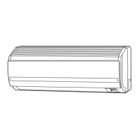
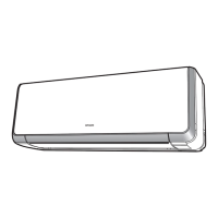
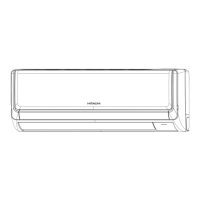
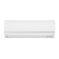
Provides identification details and physical dimensions for the air conditioner models.
Explains the functions and layout of the control panel on the indoor unit.
Describes the purpose and location of the duct filter for air exchange.
Details the functionality and operation of the wireless remote control for the air conditioner.
Important user guidelines and safety tips for operating the air conditioner with installed filters.
Explains the various operational modes and features available for the air conditioner.
Describes how the air conditioner automatically adjusts its operation based on environmental conditions.
Details the automatic restart function after a power failure and its configuration.
How to directly select the heating operation mode using the remote control.
Steps for manually adjusting heating operation parameters like fan speed and temperature.
Information on the automatic defrosting process during heating operation.
Explains the specific functions and settings related to dehumidification.
Instructions for operating the air conditioner in cooling mode.
How to directly select the cooling operation mode.
Steps for manually adjusting cooling operation parameters.
Details on operating the fan independently or in conjunction with other modes.
Explains the operation of the two-way air exchange system for ventilation.
How the unit automatically manages air exchange based on detected air quality.
Guides on setting various timer functions for operation scheduling.
Procedure for cancelling any set timer reservations.
Instructions on how to adjust the direction of airflow using the unit's deflectors.
How to safely open the front panel to access internal components.
Steps for removing the air intake pre-filters for cleaning or replacement.
Procedure for removing the specialized filter cases for cleaning.
Steps for removing the exhaust pre-filter.
Guidance on checking the condition of filters after removal.
Instructions for washing the unit's filters with water.
Procedure for correctly reinstalling the specialized filter cases.
Steps for properly reattaching the air intake pre-filters.
How to correctly close the front panel after maintenance.
Specific steps for cleaning the pre-filter component.
Instructions for cleaning the unit's front panel and top grill.
Steps to prepare the unit for extended periods of non-operation.
Guide on replacing the batteries in the remote control unit.
Information on the address changing switch and its function.
Details on how the unit provides heating and its performance characteristics.
Explains the unit's functions for cooling and reducing humidity.
General overview of the unit's operational capabilities.
Explains the diverse operational modes and features of the air conditioner.
Guides on setting timers for automatic operation and sleep mode.
Explains the functionality and operation of the air purification system.
Details the operation of the two-way air exchange system for improved ventilation.
Further explanation of the sleep timer and its effects on operation.
Instructions on how to adjust the direction of airflow using the unit's deflectors.
Diagram illustrating the construction and dimensions of the indoor unit.
Diagram illustrating the construction and dimensions of the outdoor unit.
Details the specifications and function of the thermostat component.
Information on the fan motor, including specifications and connection details.
Lists key electrical components used in the outdoor unit.
Describes the unit's performance and characteristics when operating in heating mode.
Explains the unit's functions for cooling and reducing humidity.
General overview of the unit's operational capabilities.
Explains the diverse operational modes and features of the air conditioner.
Guides on setting timers for automatic operation and sleep mode.
Explains the functionality and operation of the air purification system.
Details the operation of the two-way air exchange system for improved ventilation.
Further explanation of the sleep timer and its effects on operation.
Explains the defrost process specifically for cooling operations.
Instructions for operating the air conditioner in dehumidifying mode.
Details the dehumidifying mode combined with sleep timer functionality.
Explains the defrost process using the reversing valve during heating.
Details the heating sleep mode and the one-more timer function.
Details the reset circuit's function in initializing the microcomputer upon power changes.
Describes the circuit responsible for receiving signals from the remote controller.
Explains the function of the buzzer circuit for audible feedback.
Details the circuit controlling the snap motors for air deflectors and dampers.
Explains the circuit that sets initial values for the microcomputer upon power-up.
Describes the power supply circuits that generate necessary voltages for unit operation.
Details the circuit responsible for driving and controlling the fan motor speed.
Explains the circuit for the ventilation fan motor and its abnormality detection.
Describes the function and circuit of the dirt sensor for air quality monitoring.
Details the functions of the main printed wiring board in the outdoor unit.
Details the functions of the power printed wiring board in the outdoor unit.
Explains the circuit designed to improve power factor and reduce harmonics.
Describes the main power conversion and distribution circuits.
Lists and explains the primary components within the power circuit.
Describes the signal transmission from the outdoor unit's microcomputer to the indoor unit.
Describes the signal transmission from the indoor unit's microcomputer to the outdoor unit.
Details the control printed wiring board involved in unit communication.
Details the power printed wiring board involved in unit communication.
Shows voltage waveforms for outdoor to indoor unit communications.
Shows voltage waveforms for indoor to outdoor unit communications.
Explains the format of data sent from the outdoor unit to the indoor unit.
Explains the format of data sent from the indoor unit to the outdoor unit.
Illustrates the waveforms associated with serial communication data.
Details the data content of messages sent from the outdoor unit.
Details the data content of messages sent from the indoor unit.
Shows the circuit diagram associated with the IPM device.
Illustrates the internal circuit diagram of the IPM module itself.
Identifies the terminal markings and symbols on the IPM module.
Contains cross-references and notes related to IPM diagnosis and failure indications.
Describes the circuit that controls overload conditions to protect components.
Details the IS OVL circuit for monitoring and limiting total system current.
Details the ID OVL circuit for monitoring and limiting compressor current.
Explains the circuit that maintains constant start current for smooth compressor operation.
Details the reset circuit that initializes the microcomputer program.
Q&A related to problems encountered during cooling operation.
Q&A related to problems encountered during dehumidifying operation.
Q&A related to problems encountered during heating operation.
Q&A regarding the auto fresh defrosting function.
Q&A related to the automatic operation mode.
Q&A regarding the nice temperature reservation feature.
Q&A related to the functionality of the infrared remote control.
Essential safety precautions to follow before performing checks and diagnostics.
Step-by-step instructions for safely discharging electrical components.
Steps for safely removing electrical components from the indoor unit.
Instructions for removing the control printed wiring board.
Steps for removing the indicating printed wiring board at the display panel.
Instructions for removing the indicating printed wiring board at the switch.
Describes the electrical parts located in the outdoor unit.
Steps for removing printed wiring boards from the outdoor unit.
Details the power factor improvement capacitor and its replacement procedure.
Steps for removing printed wiring boards from the outdoor unit.
Specific instructions for handling the power factor improvement capacitor during servicing.
Specific warnings and precautions when working with ICP (IC Protector) components.
Describes how the unit indicates detected failures through lamps and blinking patterns.
Explains how failure data is stored and can be accessed for analysis.
Details the function for diagnosing communication circuit issues.
Step-by-step guide to view previously stored failure information.
Procedure for clearing the stored failure diagnosis data.
Procedures for diagnosing electrical issues in both indoor and outdoor units.
Steps for diagnosing problems related to the unit's refrigerating cycle.
Troubleshooting steps when the unit fails to power on or operate.
Troubleshooting steps when the indoor fan fails to operate, with others normal.
Troubleshooting steps when the air deflectors fail to move, with others normal.
Steps for checking the control printed wiring board and its power circuit.
Diagnosing and resolving issues where the ventilation fan motor fails to operate.
Initial steps to begin diagnosing ventilation fan motor issues.
Diagnosing and resolving issues related to the two-way air exchange lamp blinking.
Initial steps to begin diagnosing two-way air exchange lamp blinking issues.
Method for testing remote control functionality using a specialized test card.
Steps for removing printed wiring boards from the outdoor unit.
Specific instructions for handling the power factor improvement capacitor during servicing.
Diagnostic steps when the outdoor unit shows no operation or abnormal behavior.
Diagnosing issues when thermistors report abnormal readings.
Diagnosing issues related to overheating detected by the OH thermistor.
Troubleshooting steps for overload protection triggering.
Diagnosing issues related to switching failures within the unit.
Troubleshooting steps for the fan motor operating at abnormal low speeds.
Diagnosing issues related to peak current cut-offs.
Troubleshooting steps when the unit stops due to a reset condition.
Steps to diagnose issues when the unit has no operation, heating, or cooling.
Procedure for checking the IPM on the main P.W.B. as part of cycle diagnosis.
Steps to operate the unit in forced cooling mode using the service switch.
Procedures for independent testing and operation of the outdoor unit.
Shows the circuit diagram associated with the IPM device.
Illustrates the internal circuit diagram of the IPM module itself.
Identifies the terminal markings and symbols on the IPM module.
Detailed steps for using a multimeter to diagnose IPM issues.
General note indicating the procedure applies to the indoor unit.
Steps for removing the front panel and air purifying unit.
Instructions for removing the top grill and front cover components.
Steps for removing the indicating P.W.B. located at the display panel.
Instructions for removing the control printed wiring board.
Steps for removing the two-way air exchange unit.
Procedure for removing the dew-free assembly.
Steps for removing the indicating P.W.B. located at the switch.
Instructions for removing the cross-flow fan and fan motor assembly.
Steps for removing electrical parts from the outdoor unit.
Steps for removing printed wiring boards from the outdoor unit.
Procedure for removing the power factor improvement capacitor.
Lists and diagrams parts specific to the indoor unit.
Lists and diagrams parts specific to the outdoor unit.
Lists and diagrams parts specific to the outdoor unit.
Lists and diagrams parts specific to the outdoor unit.
| Type | Split System |
|---|---|
| Cooling Capacity | 2.5 kW |
| Heating Capacity | 3.2 kW |
| Power Supply | 220-240V, 50Hz |
| Refrigerant | R410A |
| Energy Efficiency Ratio (EER) | 3.21 |
| Indoor Unit Weight | 9 kg |
| Outdoor Unit Noise Level | 48 dB(A) |