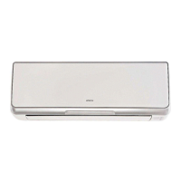
Do you have a question about the Hitachi RAS-10FXG and is the answer not in the manual?
Basic checks and initial troubleshooting steps for unit operation.
Setting of rotary and dip switches for indoor and outdoor units.
Procedures for verifying electrical wiring connections and compliance.
Simple checking of unit status using the outdoor unit's 7-segment display.
Method for operating the unit in emergency when the inverter compressor fails.
Troubleshooting steps for power supply failures affecting indoor units.
Diagnosing and resolving issues with communication between switches and units.
Troubleshooting common device abnormalities when no alarm code is indicated.
Detailed procedures for diagnosing issues using alarm codes and check modes.
Table listing alarm codes, contents of abnormality, and leading causes.
Step-by-step troubleshooting guidance based on specific alarm codes.
Using the remote control's check mode for diagnosing unit issues.
Checking methods using the 7-segment display for troubleshooting.
Details on the functions of rotary switches, dip switches, and LEDs on PCBs.
Methods for self-checking PCBs, remote control switches, and other components.
Procedure for testing PCBs using the remote control switch.
Method for self-checking the remote control switch and its LCD indications.
Self-checking procedures for indoor unit PCBs, excluding specific models.
Procedure for self-checking the 7-day timer for maintenance and malfunction.
Procedure for self-checking the central station for maintenance and malfunction.
High voltage discharge work and procedures for checking major components.
Procedures for conducting test runs via remote control or outdoor unit.
Procedures for conducting test runs via remote control switch.
Setting dip switches on the outdoor unit for test run operation.
Checklist for performing test runs on FSG and FS3 series units.
Procedures for servicing and disassembling outdoor unit components.
Steps to remove screws and detach the air intake grille from the unit.
Procedure for removing the front service panel by unscrewing and lifting.
Instructions for removing fan guard nets by unscrewing them.
Steps to remove fan guard nets, cap nuts, and propeller fans from the motor shaft.
Procedure for removing compressors, including releasing lace and Td thermistor.
Steps for removing compressors for various models, excluding MC1 and MC2.
Procedure for removing compressors for MC1 and MC2 models.
Steps for removing compressors for MC3 and MC4 models.
Procedure for removing pressure sensors and switches after refrigerant collection.
Steps to remove the coil for the reversing valve after removing the front panel.
Procedure for removing solenoid valve coils after removing the front panel.
Steps to remove thermistors for liquid and gas pipes from the heat exchanger.
Procedure for removing the reversing valve by disconnecting pipes and wiring.
Steps for removing the reversing valve for specific high-capacity models.
Procedure for removing electrical components like PCBs and modules.
Steps for removing electrical components for high-capacity models.
Specific disassembly and maintenance steps for indoor units.
Instructions for removing the long life filter from the air intake grille.
Procedure for removing the PCB by loosening screws and pulling out.
Steps for removing the fan assembly and motor from the unit.
Procedure to remove thermistors from the pipes after removing covers.
Steps for removing the electronic expansion valve coil.
Procedure to remove the float switch using two spanners.
Steps to remove the drain pump fixed on the service cover.
Procedure for removing the drain pan after loosening screws.
Maintenance procedures for larger capacity in-the-ceiling indoor units.
Instructions for removing the long life filter.
Procedure for removing the PCB by clamping holders and pulling.
Steps for removing the fan and motor assembly.
Procedure to remove expansion valve and thermistors from the heat exchanger.
Servicing instructions for 4-way cassette indoor units.
Instructions for removing the long life filter by opening the air intake grille.
Steps to remove the air intake grille by lifting and releasing its chain.
Procedure for removing the electrical box cover after opening the air intake grille.
Steps to remove the optional air panel after removing covers and connectors.
Procedure for removing fan runner and motor assembly.
Steps to remove the bell-mouth, nuts, washers, and earth wire.
Procedure for removing the PCB by pinching holders and disconnecting wires.
Steps to remove the drain pan after loosening screws.
Procedure for removing the drain-up mechanism and its fixing plate.
Steps to remove the float switch by loosening a resin nut.
Steps to remove thermistors for liquid and gas pipes from the heat exchanger.
Steps for removing the electronic expansion valve coil.
Procedure to remove the automatic louver motor and its cover.
Maintenance procedures for 2-way cassette indoor units.
Instructions for removing the long life filter and air intake grille.
Procedure for removing the electrical box cover.
Steps to remove the optional air panel after removing covers and connectors.
Procedure for removing the fan runner and fan motor assembly.
Steps to remove the PCB by pinching holders and disconnecting wires.
Procedure to remove the float switch after removing covers and screws.
Steps to remove the drain-up mechanism after disconnecting wires and screws.
Procedure for removing the drain pan after removing plates and screws.
Steps to remove thermistors for liquid and gas pipes from the heat exchanger.
Steps for removing the electronic expansion valve coil.
Procedure to remove the automatic louver motor and its cover.
Servicing steps for wall-mounted indoor units.
Instructions for removing the air filter by pressing and pulling the grille.
Steps to remove the front panel by pressing, unscrewing, and lifting.
Procedure to remove the AS motor from the louver shaft.
Steps to remove thermistors for various pipes and air sensors.
Procedure for removing the electrical box and its cover.
Steps to remove the indoor PCB by releasing catches and connectors.
Procedure for removing the drain pan by releasing catches.
Steps to remove the heat exchanger by releasing catches and screws.
Procedure for removing the fan motor and its assembly.
Steps for removing the electronic expansion valve coil.
Maintenance procedures for floor-standing indoor units.
Instructions for removing the air intake grille.
Steps to remove the air filter by pulling the knob.
Procedure for removing discharge air grilles by sliding them.
Steps to remove the front cover after removing screws.
Procedure for removing the fan motor assembly.
Steps to remove the PCB by releasing catches and connectors.
Steps to remove thermistors for liquid and gas pipes.
Disassembly and servicing for floor-concealed indoor units.
Instructions for removing the air filter.
Steps to remove the front lower and upper covers.
Procedure for removing the fan motor.
Steps to remove PCBs.
Procedure to remove thermistors for liquid and gas pipes.
Maintenance procedures for ceiling-mounted indoor units.
Instructions for removing air filter and intake grille.
Steps to remove the side cover by releasing catches.
Procedure for removing discharge air grilles.
Steps to remove the fan motor assembly.
Procedure for removing the bearing.
Steps to remove the coupling.
Procedure to remove the automatic louver motor.
Steps to remove thermistors and expansion valve coil.
Procedure for checking the electronic expansion valve coil.
Steps to remove the PCB.
Structure and servicing of the total heat exchanger unit.
Overview of the total heat exchanger structure.
Procedure for removing electrical parts from the control box.
Steps to remove air filters and the total heat exchanger element.
Procedure for removing fan motors for supply and discharge air.
Instructions for cleaning the air filter.
Procedure for cleaning the total heat exchanger element.
Procedures for cleaning the heat exchangers of various indoor unit types.
List of tools and equipment needed for cleaning indoor unit heat exchangers.
Cleaning procedures specific to in-the-ceiling indoor units.
Steps for cleaning 4-way cassette indoor units.
Procedure for cleaning 2-way cassette indoor units.
Steps for cleaning wall-mounted indoor units.
Procedure for cleaning floor type and concealed indoor units.
Steps for cleaning ceiling-mounted indoor units.
Steps for safely collecting refrigerant when replacing indoor units.
Specifications and arrangement details for inverter power units.
Specifications for inverter units operating on specific power sources.
Specifications for inverter units operating on 220V, 60Hz power.
Diagram showing the layout of inverter power unit components.
Timing charts illustrating inverter operation sequences.
Details on the inverter's protective functions against voltage and current issues.
Explanation of the overload control mechanism for the inverter.
Explanation of the AC Chopper control concept and specifications.
Specifications for the AC Chopper, including current and voltage ratings.
Circuit diagrams and structural outlines of the AC Chopper.
Details on the operation and stoppage of auto-louver mechanisms.
Operation and stoppage principles of auto-louver for 4-way cassette units.
Details on the operation and stoppage of auto-louver for 2-way cassette units.
Operation and stoppage principles of auto-louver for ceiling units.
Details on the operation and stoppage of auto-louver for wall-mounted units.
Principles of operation, structure, and reliability of scroll compressors.
Explanation of features ensuring low vibration and sound in scroll compressors.
Step-by-step explanation of the scroll compressor's compression process.
Diagrams illustrating the structure of scroll compressors and their types.
Specifications and locations of thermistors for indoor and outdoor units.
Position and characteristics of thermistors used in indoor units.
Location and characteristics of thermistors for outdoor units.
Details on electronic expansion valves for outdoor and indoor units.
Specifications and wiring diagrams for outdoor unit expansion valves.
Specifications and wiring diagrams for indoor unit expansion valves.
Operation and characteristics of high and low pressure sensors.
Operation of high pressure control using the sensor.
Operation of low pressure control using the sensor.
Explanation of the high pressure protection device and its function.
Specifications and circuit diagram for the noise filter.
Function and specifications of capacitors used in the inverter circuit.
Function and specifications of the reactor (DCL).
Details on optional functions for specific indoor unit models.
Control for system start/stop using remote signals via wiring or switches.
Automatic start/stop based on power supply status.
Automatic restart after power failure.
Using an external thermostat for indoor unit temperature control.
Controlling the unit based on remote temperature sensor readings.
Changing operation mode via external contact signals.
Utilizing signals to check operation or interlock with other equipment.
Input/output settings and optional functions for a different range of indoor units.
Procedures for changing input/output settings via PCB connectors and remote switch.
Using remote control thermistor for temperature control instead of unit's.
Controlling system start/stop from a remote place using various signals.
Automatic start/stop based on power supply status.
Automatic restart after power failure.
Using external thermostat for indoor unit control.
Controlling unit based on average of inlet air and remote temperature sensors.
Changing operation mode via external contact signals.
Delaying total heat exchanger start for specific operations.
Utilizing contact signals for cooling/heating mode changes or interlocks.
External signal inputs and outputs for outdoor unit control.
Handling of demand input terminals for compressor control.
Procedure for stopping the compressor and fan motor via input terminals.
Controlling compressor frequency based on demand current limits.
Fixing the operation mode to cooling or heating via input terminals.
Function of the snow sensor for protecting outdoor units.
Changing defrosting conditions using dip switch settings.
Controlling indoor fan operation during heating thermo-OFF cycles.
Enabling year-round heating operation under high outdoor temperatures.
Enabling year-round cooling operation under low outdoor temperatures.
Setting night shift for reduced sound operation, affecting cooling capacity.
Utilizing signals from the outdoor unit PCB for alarms and operation status.
Overview of remote control switches and their parts.
Identification of parts on the remote control switch (PC-P1H/PC-2H2).
Controlling multiple indoor units simultaneously with one remote switch.
Setting up main and sub remote control switches for dual control.
Setting optional functions for indoor units using the remote control.
Detailed list and explanation of optional functions settable via remote control.
Details on the PC-LH3 wireless remote control switch and its parts.
Identification of parts of the PC-LH3 wireless remote control switch.
Procedure for identifying indoor units installed adjacently.
Controlling multiple indoor units simultaneously with a wireless remote.
Operating the unit using the emergency switch when remote is unavailable.
Setting optional functions via dip switches on the receiver kit.
List of optional functions configurable via wireless remote dip switches.
Operation and functions of the 7-day timer (PSC-5T).
Identification of parts of the PSC-5T 7-day timer.
Features and operation of the central station PSC-5S.
Identification of parts for the PSC-5S central station.
Case study on compressor failure caused by low refrigerant charge.
Troubleshooting a case of poor cooling due to long refrigerant piping.
Addressing abnormal noise issues in in-the-ceiling indoor units.
Troubleshooting scenario involving alarm code "31" and system stoppage.
Diagnosing and resolving cooling issues caused by inadequate outdoor unit spacing.
Important considerations for designing and installing SET-FREE FXG/FX3 series systems.
Guidelines for selecting appropriate drain pipe sizes based on flow volume.
Safety precautions and calculations related to HCFC gas concentration.
Routine maintenance checks for indoor and outdoor units.
Using the 7-segment display for service and maintenance records.
Recording service and maintenance data using the remote control switch.
General service and maintenance record log.
| Type | Split System |
|---|---|
| Heating Capacity | 3.2 kW |
| Power Supply | 220-240V, 50Hz |
| Refrigerant | R410A |
| Indoor Unit Weight | 9 kg |
| Noise Level (Outdoor) | 50 dB(A) |


 Loading...