Do you have a question about the Hitachi RAS-25FH6 and is the answer not in the manual?
Lists the main sections and page numbers of the service manual.
Identifies the Hitachi air conditioner models covered by this manual.
Essential safety guidelines to follow before and during repair work on the unit.
Details on handling specific electronic components like ICs and PC boards safely.
Important notes regarding normal operation, thunderstorms, and power failures.
Lists key components like fan motor, compressor, and their respective specifications.
Critical safety measures to observe during the installation process of the air conditioner.
Safety instructions for operating the air conditioner, including thunderstorm warnings.
Safety guidelines for handling the unit during maintenance and relocation.
Identifies and describes the function of various parts of the indoor unit.
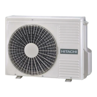
Identifies and describes the function of various parts of the outdoor unit.
Explains the meaning of indicator lamps on the indoor unit.
Details the buttons and display of the remote controller for operating the unit.
Explains how the unit automatically selects cooling or heating based on room temperature.
Describes the unit's behavior after a power failure and how to manage it.
Instructions for using the heating function, including temperature and fan speed settings.
Instructions for using the dehumidifying function, including temperature and fan speed settings.
Instructions for using the cooling function, including temperature and fan speed settings.
Instructions for using the fan-only mode as an air circulator or for drying.
Step-by-step guide to setting the timer to turn the unit off.
Step-by-step guide to setting the timer to turn the unit on.
Guide for setting both an ON and OFF timer for scheduled operation.
Instructions on how to cancel a set timer reservation.
Guide on how to set the sleep timer for automatic shutdown.
Instructions for adjusting the direction of airflow from the indoor unit's louvers.
Steps for safely replacing batteries in the remote control unit.
Procedure for cleaning the air filter to maintain unit efficiency and air quality.
Instructions for cleaning the exterior front panel of the indoor unit.
Steps for preparing the unit for extended periods of non-operation.
Information on the unit's heating and cooling performance under various conditions.
Key items to check periodically to ensure proper and safe operation.
A table to guide troubleshooting based on specific operating conditions and checks.
Explains common noises that may occur during normal operation and are not indicative of a fault.
Illustrates the flow of refrigerant during cooling, dehumidifying, and defrosting cycles.
Provides detailed measurements and installation space requirements for the indoor unit.
Provides detailed measurements and installation space requirements for the outdoor unit.
Details the temperature settings and indications for the thermostat function.
Provides information on the fan motor's power source, output, and wiring connections.
Lists major electrical components used in the outdoor unit and their ratings.
Details the compressor type, power source, output, winding, and resistance.
Illustrates the electrical connections between the indoor and outdoor units and their components.
Shows the overall circuit layout and component interconnections for the unit.
Illustrates the functional relationships between the indoor and outdoor units and their main modules.
Explains how to select operation modes and control fan speed for various conditions.
Details the logic for judging and controlling operation based on room and outdoor temperatures.
Describes the different stages of cooling operation including fan and compressor speed.
Explains how temperature judgments affect compressor speed during cooling.
Details on sleep mode during cooling and the defrost cycle in cooling.
Details on sleep mode during dehumidifying operation.
Describes the different stages of heating operation including fan and compressor speed.
Explains the logic for controlling heating operation based on temperature and conditions.
Explains the defrosting process using the reversing valve and its timing.
Details on sleep mode during heating operation.
Illustrates the refrigerant flow for cooling, dehumidifying, and defrosting modes.
Illustrates the refrigerant flow specifically for the heating mode.
Explains how the reset circuit initializes the microcomputer during power on/off.
Describes the receiver circuit and the buzzer circuit for signal reception and feedback.
Details the auto sweep motor circuit and microcomputer output signals.
Explains initial settings, power supply, and voltage regulation for unit components.
Details the PWM control and feedback mechanism for the DC fan motor.
Explains the power circuit's function and key components like diodes and inductors.
Details the roles of capacitors, diodes, inductors, and resistors in the power circuit.
Describes the circuit enabling communication between indoor and outdoor microcomputers.
A schematic showing the interface circuit for microcomputer communication.
Details the structure and content of communication data between units.
Illustrates an example of communication waveforms and data exchange.
Explains the IPM circuit and its role in driving the compressor motor.
Describes the switching order and voltage waveforms within the IPM module.
Shows the IPM circuit diagram and self-diagnosis lamp codes for IPM faults.
Details the power circuit responsible for supplying various voltages to the P.W.B.
Lists the voltage specifications for different outputs and potential failure modes.
Describes circuits connected to the microcomputer, including peak current cutoff and overload control.
Explains the circuit that detects and stops operation on over-current.
Details the circuit that protects components by controlling compressor load and speed.
Explains the system for judging and controlling overload based on current and rotation speed.
Describes the software control method for maintaining smooth compressor start current.
Explains the reset circuit's function and waveforms during power on/off.
Addresses common issues and their solutions during cooling operation.
Addresses common issues and their solutions during dehumidifying operation.
Addresses common issues and their solutions during heating operation.
Covers questions about auto-fresh defrosting, auto operation, and temperature reservation.
Addresses questions related to timer settings and remote control functionality.
Explains fan speed behavior in auto mode and potential noises from the unit.
Addresses questions about temperature differences and initial airflow.
Critical safety warnings and diagrams related to high voltage during troubleshooting.
Step-by-step guide on how to safely discharge smoothing capacitors before service.
Step-by-step guide for removing the front panel and cover of the indoor unit.
Instructions for disassembling the control and indicating printed circuit boards.
Specific warnings related to servicing the IC protector and potential failures.
Guidance on safely handling connectors and avoiding damage during testing.
Explains how indicator lamps (timer lamp, LD301) signal detected failures.
Lists blinking patterns of the timer lamp and their corresponding reasons and possible causes.
Explains the meaning of diagnostic lights (LD303, LD302, LD301) and their associated error conditions.
Guides users through checking unit parts and the refrigeration cycle based on symptoms.
A flowchart to diagnose and resolve issues when the unit does not power on.
Flowcharts to diagnose problems with the indoor fan or air deflector movement.
Guides troubleshooting of the control board's power circuit and associated components.
Steps to verify battery status, signal transmission, and overall remote control functionality.
Flowchart for diagnosing power issues and connection problems in the outdoor unit.
Guides troubleshooting of the outdoor fan motor and main P.W.B. based on self-diagnosis codes.
Steps to verify AC power input, terminal connections, and power supply components.
Flowchart to diagnose and resolve communication errors between indoor and outdoor units.
Verifies internal wiring and terminal connections for proper power output.
Diagnoses communication errors and checks 35V power output and related components.
Guides troubleshooting of the thermistor circuit, including connector and continuity checks.
Addresses issues related to OH thermistor temperature rise and overload conditions.
Guides troubleshooting for switching failures and abnormal low speed operation.
Covers troubleshooting for the intelligent power module (IPM) and the reset circuit.
Step-by-step instructions for adjusting the temperature shift values using the remote controller.
Troubleshooting procedure for issues related to gas leakage or compressor defects.
Instructions for operating the outdoor unit independently for testing or service.
Details the internal circuit diagram and terminal symbols of the IPM module.
Provides a procedure for testing the IPM module using a multimeter.
Step-by-step guide for removing the front panel and cover of the indoor unit.
Instructions for disassembling the control and indicating printed circuit boards.
Instructions for removing the tangential fan and motor from the indoor unit.
Steps for removing electrical components from the outdoor unit's enclosure.
An exploded view illustrating the parts of the indoor unit.
A detailed list of part numbers and names for the indoor unit.
An exploded view illustrating the parts of the outdoor unit.
A detailed list of part numbers and names for the outdoor unit.
| Type | Split System |
|---|---|
| Cooling Capacity | 2.5 kW |
| Heating Capacity | 3.2 kW |
| Power Supply | 220-240V, 50Hz |
| Energy Efficiency Ratio (EER) | 3.21 |
| Coefficient of Performance (COP) | 3.61 |
| Refrigerant | R410A |
| Indoor Unit Weight | 9 kg |
| Noise Level (Outdoor) | 50 dB |