EasyManua.ls Logo

Hitachi RAS-25CNH2 Service Manual

Hitachi RAS-25CNH2
81 pages
To Next Page IconTo Next Page
Page #1 background imageLoading...
Page #1 background image
NO. 0081E
SERVICE MANUAL
PM
TECHNICAL INFORMATION
FOR SERVICE PERSONNEL ONLY
SPECIFICATIONS
CONTENTS
SPECIFICATIONS --------------------------------------------------------------5
HOW TO USE -------------------------------------------------------------------6
CONSTRUCTION AND DIMENSIONAL DIAGRAM ---------------- 22
MAIN PARTS COMPONENT --------------------------------------------- 23
PRINTED WIRING BOARD LOCATION DIAGRAM---------------- 25
BLOCK DIAGRAM ------------------------------------------------------------ 33
DESCRIPTION OF MAIN CIRCUIT OPERATION ------------------ 35
SERVICE CALL Q & A ----------------------------------------------------- 67
TROUBLE SHOOTING ------------------------------------------------------ 70
PARTS LIST AND DIAGRAM--------------------------------------------- 80
RAS-25CNH2
RAC-25CNH2
REFER TO THE FOUNDATION MANUAL
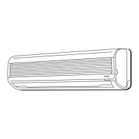
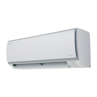
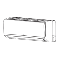
INDOOR UNIT
RAS-25CNH2
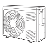
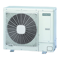
OUTDOOR UNIT
RAC-25CNH2
WALL TYPE
SPECIFICATIONS AND PARTS ARE SUBJECT TO CHANGE FOR IMPROVEMENT
ROOM AIR CONDITIONER
INDOOR UNIT + OUTDOOR UNIT
APRIL 1998
H.A.P.M.
TYPE
MODEL
1ø 220V – 240V 50HzPOWER SOURCE
910 (190 ` 1,150) [COOL] / 1,250 (160 ` 1,350) [HEAT]TOTAL INPUT
4.20 ` 3.85 [COOL] / 5.75 ` 5.25 [HEAT]TOTAL AMPERES (RATED / MAX.)
COOLING CAPACITY
HEATING CAPACITY
DIMENSIONS
NET WEIGHT
(W)
(A)
(kW)
(B.T.U./h)
(kW)
(B.T.U./h)
W
H
D
(kg)
(mm)
2.50 (0.90 ` 2.80)
8,870 (3,070 ` 9,550)
3.60 (0.90 ` 4.00)
12,280 (3,070 ` 13,650)
744
248
168
5.5
700
570
210
29
RAS-25CNH2
RAC-25CNH2

Other manuals for Hitachi RAS-25CNH2

Question and Answer IconNeed help?

Do you have a question about the Hitachi RAS-25CNH2 and is the answer not in the manual?

Hitachi RAS-25CNH2 Specifications

General IconGeneral
BrandHitachi
ModelRAS-25CNH2
CategoryAir Conditioner
LanguageEnglish

Summary

Safety During Repair Work

Working Standards for Preventing Breakage of Semiconductors

Specifications

Names and Functions of Each Part

Names and Functions of Remote Control Unit

Automatic Operation

CONDITION OF AUTOMATIC OPERATION

Details operating conditions for automatic mode based on room temperature.

Adjusting the Air Deflector

Maintenance

AIR FILTER

Details cleaning and maintenance procedures for the air filter.

Washable Suction Grille

Instructions for cleaning the washable suction grille.

Construction and Dimensional Diagram

Main Parts Component

THERMOSTAT

Provides specifications and model details for the thermostat.

FAN MOTOR

Details specifications, connection, and resistance for the fan motor.

Compressor Motor

Printed Wiring Board Location Diagram

POWER P.W.B.

Diagram showing the layout of components on the power P.W.B.

MAIN P.W.B.

Diagram illustrating the component layout of the main P.W.B.

Block Diagram

Description of Main Circuit Operation

DC Fan Motor Drive Circuit

Describes the circuit for driving the indoor DC fan motor.

Power Circuit

Explains the AC-DC conversion and voltage boosting in the power circuit.

Indoor/Outdoor Interface Circuit

Details the circuit enabling communication between indoor and outdoor units.

Power Module Circuit

Illustrates the power module and its peripheral circuit for compressor drive.

Power Circuit for P.W.B.

Details the switching power circuit for the P.W.B.

Reversing valve control circuit

Explains the circuit that controls the reversing valve based on operation conditions.

Rotor Magnetic Pole Position Detection Circuit

Describes the circuit detecting rotor position for motor control.

Temperature Detection Circuit

Explains circuits for detecting compressor and heat exchanger temperatures.

[Serial Communications Format during Normal Communications]

Drive Circuit

Upper Arm Drive Circuit

Explains the circuit that drives the upper arm transistors of the power module.

Lower Arm Drive Circuit

Explains the circuit that drives the lower arm transistors of the power module.

HIC and Peripheral Circuits

Peak current cut off circuit

Details the circuit that detects and cuts off peak current to protect components.

Overload control circuit (OVL control circuit)

Describes the circuit that reduces compressor speed under overload conditions.

Service Call Q & A

Trouble Shooting

PRECAUTIONS FOR CHECKING

Lists safety precautions and voltage checks before troubleshooting.

Checking the Indoor/Outdoor Unit Electrical Parts and Refrigerating Cycle

Checking the Outdoor Unit Electrical Parts

PAM (Power Active Module) Circuit

Parts List and Diagram

Related product manuals