Do you have a question about the Hitachi RAS-25CNH1 and is the answer not in the manual?
Lists the main sections and their corresponding page numbers.
Outlines essential precautions for handling electronic components.
Provides detailed dimensions for the outdoor unit mounting stand.
Explains the allowed directions for piping installation.
Lists warnings and cautions for the installation process.
Lists warnings and cautions for operating the unit safely.
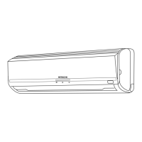
Details parts and functions of the indoor unit.
Details parts and functions of the outdoor unit.
Explains the features and operation of the remote controller.
Details the conditions and settings for automatic operation.
Describes how the dehumidifying function operates based on temperature.
Explains how AUTO fan speed adjusts during cooling/heating operations.
Explains how to set the timer to turn the unit off.
Explains how to set the timer to turn the unit on.
Explains the sleep timer operation and notes.
Warns about potential condensation issues with the air deflector.
Explains the use of the temporary switch for operation.
Provides warnings and advice on temperature and ventilation.
Details the procedure for cleaning and maintaining the air filter.
Lists points for regular inspection by qualified service personnel.
Lists checks to perform before requesting service.
Illustrates the construction and dimensions of the indoor unit model.
Illustrates the construction and dimensions of the outdoor unit model.
Provides thermostat specifications and operating points.
Provides fan motor specifications, connection, and resistance values.
Displays the circuit diagram for the RAS-25CNH11 model.
Illustrates the overall system operation and component interaction.
Lists operational data including mode, temperature, and fan speed parameters.
Describes cooling operation, fan speed, and compressor control.
Describes dehumidifying operation and fan speed control.
Describes heating operation, fan speed, and compressor control.
Lists cooling operation parameters like TCMAX and dewing conditions.
Explains the cooling defrost operation and its parameters.
Provides important notes regarding the Cool rhythm operation.
Provides notes on heating operation, including hot dash and preheating.
Provides notes on defrost inhibit period, maximum speed, and defrost period.
Explains the function and operation of the reset circuit.
Shows rotation angle and time per step for the auto sweep motor.
Explains the room temperature thermistor circuit and voltage output.
Explains the heat exchanger thermistor circuit and its control functions.
Provides references for troubleshooting power circuit faults.
Shows the circuit diagram of the power module and its related components.
Shows the circuit diagram for the upper arm drive.
Shows the circuit diagram for the lower arm drive.
Shows the microcomputer and its peripheral circuits.
Shows the peak current cut-off circuit and its operational waveforms.
Explains the external overload judgement circuit.
Shows circuits to which various modulation signals are transferred.
Shows the circuit diagram for temperature detection.
Shows the circuit diagram for the reset circuit.
Illustrates the refrigerating cycle diagram for cooling operation.
Addresses common issues and questions during cooling operation.
Addresses common issues and questions during dehumidifying operation.
Provides essential safety precautions before performing checks.
Outlines the diagnostic process for electrical parts and the cycle.
Instructs to check the refrigerating cycle for proper operation.
Lists self-diagnosis codes and their corresponding details and check points.
Specifies the main check points for each self-diagnosis code.
Describes how to check the remote using a video monitor.
Explains how to build and use a checker for the remote control.
Outlines the diagnostic process for electrical parts and the cycle.
Identifies the power module model and its basic structure.
Shows circuit diagrams of the power module and its related components.
Cautions about indicator behavior and connections when checking the power module.
Details how to judge between gas leakage and compressor defects.
Provides a troubleshooting flowchart for non-operation, heating, and cooling issues.
Shows an exploded view diagram of the RAS-25CNH11 model parts.
Shows an exploded view diagram of the RAC-25CNH11 model parts.
| Cooling Capacity | 2.5 kW |
|---|---|
| Heating Capacity | 3.2 kW |
| Energy Efficiency Ratio (EER) | 3.21 |
| Power Supply | 220-240V, 50Hz |
| Refrigerant | R410A |
| Weight (Indoor Unit) | 8.5 kg |
| Weight (Outdoor Unit) | 28 kg |
| Outdoor Unit Noise Level | 48 dB(A) |
| Coefficient of Performance (COP) | 3.61 |
| Type | Split System |