Do you have a question about the Hitachi RAS-24MH1 and is the answer not in the manual?
Technical data of the unit's electrical and physical properties.
Basic operation guide for the air conditioner unit.
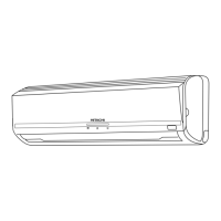
Identification of indoor and outdoor unit components.
Description of indoor unit parts and their functions.
Description of outdoor unit parts and their functions.
Detailed explanation of the remote control's features and operation.
Functions and operation of the remote control unit.
Advanced operational modes and special features of the unit.
How the unit automatically selects operating modes based on conditions.
Step-by-step instructions for operating the unit in heating mode.
Step-by-step instructions for operating the unit in dehumidifying mode.
Step-by-step instructions for operating the unit in cooling mode.
Instructions for using the fan-only mode for air circulation.
Guide for setting various timer functions for operation control.
Guide for programming the sleep timer for automatic shutdown.
Critical safety protocols and precautions for technicians during repairs.
Guidelines for handling sensitive electronic components to prevent damage.
General safety warnings and precautions for users to ensure safe operation.
Procedures for routine unit upkeep and cleaning.
Instructions for cleaning the unit's pre-filter to maintain performance.
Instructions for cleaning the removable front panel of the unit.
Scheduled maintenance checks to ensure long-term reliability and performance.
Physical size, layout, and installation dimensions of the unit.
Dimensional details and specifications for the indoor unit.
Dimensional details and specifications for the outdoor unit.
Detailed specifications of key internal components like motors and sensors.
Thermostat specifications and operation details.
Specifications and connection details for the indoor fan motor.
Specifications and connection details for the outdoor fan motor.
Specifications and connection details for the compressor motor.
Electrical connection layout for the entire air conditioning system.
Electronic circuit schematics for various functional parts of the unit.
Circuit diagram specific to the remote control unit's functions.
Component placement diagrams for the main Printed Wiring Boards.
Location diagram for the main Printed Wiring Board (PWB).
High-level system architecture overview showing component interactions.
Diagram illustrating the flow of refrigerant during different operating modes.
Answers to common questions encountered during service calls.
Comprehensive guide to diagnosing and fixing various operational issues.
Safety measures and precautions to follow during diagnostic checks.
Diagnostic steps for specific timer lamp error codes.
Procedures for checking electrical parts and the refrigerating cycle.
Diagnosing faults indicated by the timer lamp blinking patterns.
Troubleshooting procedures for indoor unit electrical components.
Diagnosing outdoor unit startup issues when receiving remote signals.
Troubleshooting procedures for indoor fan failures when other functions are normal.
Troubleshooting procedures for air deflector movement issues.
Diagnosing complete system shutdown after partial operation.
Troubleshooting procedures for the main Power circuit board.
Troubleshooting procedures for outdoor unit electrical components.
Performing the unit's self-diagnostic function to identify faults.
Guide to operating the outdoor unit using the test switch for diagnostics.
Understanding the meaning of self-diagnosis LED indicator patterns.
Troubleshooting procedures for the remote control unit.
Diagnosing issues related to gas leaks and compressor defects in the refrigerant cycle.
List of all replaceable parts with corresponding diagrams and part numbers.
Parts list and diagram for the indoor unit.
Parts list and diagram for the outdoor unit.
| Brand | Hitachi |
|---|---|
| Model | RAS-24MH1 |
| Category | Air Conditioner |
| Language | English |