9 Electrical and control settings
System wiring diagram
TCGB0123 rev.2 - 10/2019
110
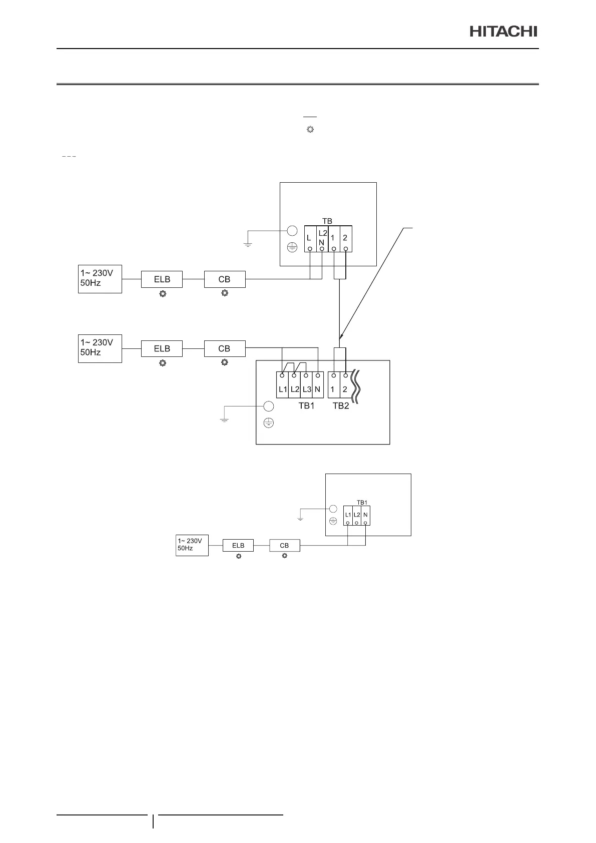
9.2 System wiring diagram
Connect the units according to the following electric diagram:
TB
:
Terminal board
:
Field wiring
CB
:
Circuit breaker
:
Field-supplied
ELB
:
Earth leakage breaker 1,2
:
Outdoor-Indoor communication
:
Internal wiring
YUTAKI (S / S COMBI)
x
x
Outdoor unit
Earth
Earth
Operating Line
(Twisted Shielded Pair Cable)
DC5V (Non-Pole Transmission,
H-LINK System)
Indoor Unit
YUTAKI M
x
YUTAKI M
RASM-VRE
Earth
 Loading...