Do you have a question about the Hitachi RAS-FSXNSE Series and is the answer not in the manual?
General information about the publication, Hitachi's policies on updates and errors, and disclaimer on data accuracy.
Explains the meaning and importance of safety symbols used throughout the manual for hazard indication.
Details the possible combinations of outdoor units for the FSXNSE series based on HP and model.
Details the possible combinations of outdoor units for the FSXNPE series based on HP and model.
Notifies users about supplementary information and the importance of reading the manual carefully before starting work.
Provides instructions for safely transporting outdoor units, covering packaging, lifting, and movement precautions.
Details safe practices for handling units, especially with forklifts, to prevent damage and ensure safety.
Explains the correct methods and precautions for lifting outdoor units using slings and cranes.
Provides center of gravity dimensions for different models, crucial for balance and stability during installation.
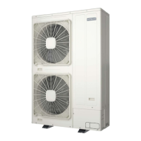
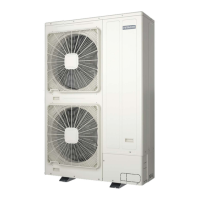
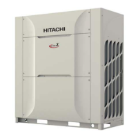
Lists and identifies the various parts of the outdoor unit for reference in diagrams and procedures.
Outlines essential environmental and location requirements for installing the outdoor unit to ensure optimal performance.
Specifies the required clearance dimensions around the outdoor unit for proper installation, ventilation, and service access.
Details installation requirements when units are placed between two walls, specifying clearances.
Details installation requirements when units are placed between three walls, specifying clearances.
Details installation requirements when units are placed within four walls, specifying clearances.
Covers general considerations for installation, including air flow, grouping, and wall clearances.
Specifies requirements for foundations, including height, drainage, and anchor bolt details for stability.
Details the correct positioning and specifications for anchorage bolts for various unit combinations.
Guides the selection of the correct optional piping connection kit based on operating mode and unit capacity.
Provides instructions and guidelines for selecting appropriate pipe sizes for refrigerant lines based on system requirements.
Details specific pipe diameters required for heat pump systems based on unit capacity and piping length.
Explains the process and precautions for connecting refrigerant pipes to the units, including accessory usage.
Lists the accessories provided with FSXNSE units for pipe connection and installation.
Lists the accessories provided with FSXNPE units for pipe connection and installation.
Highlights crucial safety and installation guidelines for outdoor unit placement and pipe routing.
Details the connection procedures for refrigerant pipes for various outdoor unit models and system types.
Provides guidance on the correct orientation and routing of refrigerant pipes to prevent issues like oil stagnation.
Specifies the correct vertical installation and slope requirements for piping connection kits for proper refrigerant flow.
Explains the correct operation, handling, and maintenance of stop valves for refrigerant control.
Provides detailed information on stop valve components, tightening torques, and service port connections.
Covers essential procedures for charging refrigerant into the system, including safety and quantity calculations.
Outlines the critical steps and safety measures for performing an air-tight test on the refrigerant system.
Explains the process of vacuuming the refrigerant system to remove moisture and air before charging.
Describes the standard procedure for vacuuming the system, including pressure checks and minimum vacuum levels.
Details an advanced method for vacuuming the system to ensure complete moisture removal for optimal performance.
Guides the calculation of additional refrigerant needed based on piping length, indoor units, and system configuration.
Explains the calculation method for additional refrigerant charge for liquid piping based on diameter and length.
Details the calculation for additional refrigerant charge for indoor units in heat pump systems based on HP.
Outlines the calculation for additional refrigerant charge based on indoor unit capacity for different HP ranges.
Explains how to calculate refrigerant charge based on the ratio of indoor to outdoor unit capacity.
Provides additional refrigerant charge amounts based on specific outdoor unit combination models.
Details additional refrigerant charge for CH-Boxes in heat recovery systems.
Specifies the maximum allowable additional refrigerant charge for the system to prevent overcharging.
Lists the factory refrigerant charge amounts for various outdoor unit models, serving as a baseline.
Provides instructions and precautions for safely charging refrigerant into the system after installation.
Explains the importance and requirements for draining condensation from the outdoor unit, especially in heating mode.
Illustrates the correct installation position for the optional drainage kit to ensure proper water drainage.
Provides general safety precautions and information regarding electrical wiring work to prevent hazards.
Lists essential checks to perform on electrical components and supply before starting installation.
Details the procedures for connecting the power supply to the outdoor and indoor units according to diagrams.
Explains the method for connecting the power source wiring to the units, including three-phase and single-phase connections.
Specifies recommended cable sizes and main breaker switch ratings for power and transmission wiring based on unit capacity.
Discusses EMC aspects, including Flicker and Harmonics, relevant to unit operation and installation compliance.
Explains Flicker and maximum allowed impedance requirements as per EN61000-3-11 for user power supply connection.
Addresses Harmonics compliance with IEC standards and potential installation restrictions related to power supply quality.
Provides diagrams and instructions for connecting electrical wiring to the outdoor unit's terminal blocks and PCB.
Guides the setting of DSW1 and RSW1 switches for configuring the refrigerant cycle number for the system.
Instructs on setting the DSW2 switch for unit capacity configuration based on model series.
Advises against changing the DSW3 setting to avoid potential abnormal operation of the unit.
Details the settings for DSW4 switches related to test runs, service operations, and system modes.
Explains the DSW5 switch settings for configuring emergency operation modes for compressors.
Guides the configuration of DSW6 for setting outdoor unit numbers and functions within a system combination.
Covers DSW7 switch settings for supply voltage and system type (Heat Pump/Heat Recovery).
Explains the DSW8 switch settings for configuring the high static pressure mode for the fan.
Provides instructions for setting DSW10 switches related to transmission and network configuration (H-LINK).
Details the settings for DSW101 switches related to inverter control and current detection configuration.
Lists essential checks to perform before starting the commissioning process, including wiring and resistance checks.
Provides a step-by-step guide for conducting the test run procedure to verify system functionality.
Details the procedure for performing a test run using the remote control switch, including menu navigation and settings.
Explains the safety devices and their specifications that protect the compressor from overpressure and other faults.