9 Servicing
RPC-(1.5-6.0)FSN3 - Ceiling type
SMGB0099 rev.0 - 12/2016
288
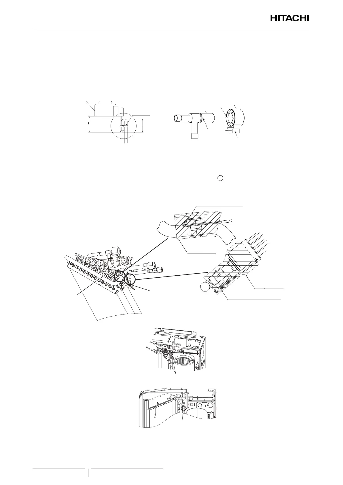
9 Tie the lead wires for a new expansion valve coil together with a plastic band as shown in the gure below.
10 Insert the new expansion valve coil for replacement into the expansion valve body. Fit the projection portions into the
detents with the wiring outlet facing up.
? NOTE
The detents are located 90º apart in a circle and the projections are located 180º apart in a circle. Fit the projection portions into the
detents. If inserting the coil incorrectly, it may cause malfunction of the expansion valve coil.
Plastic Band
New Electronic Expansion
Valve Coil
30+5
25+5
Plastic band
New electronic expansion valve coil
Projection
Detent
Expansion Valve Body
Expansion Valve Coil
Wiring Outlet
of Expansion Valve Coil
Projection
Expansion valve body
Expansion valve coil
Detent
Wiring outlet of expansion
valve coil
Notes for Mounting Pipe Thermistors and Expansion Valve Coil
• When mounting the pipe thermistors, pay attention to the outlet direction and position of the lead wires. Seal the
thermistors with butyl sheets after mounting them.
• Run the lead wires for the expansion valve coil along the outside of the pipe (
1
). Tie the wires and the pipe
thermistors in a bundle at 2 portions with plastic bands as shown in the gure below.
• Attach the xing plate for the liquid and gas pipes carefully so that the lead wires are not pinched.
Butyl Sheet
Liquid Pipe Thermistor
Butyl Sheet
1
e
Gas pipe thermistor
Butyl sheet
Butyl sheet
Liquid pipe thermistor
Plastic band
Pipe
Plastic Bands
Make sure the lead wires
are not pinched.
Plastic bands
Make sure the lead wires
are not pinched

 Loading...


