4 Electrical and control settings
Wiring diagrams for indoor units and complementary systems
SMGB0099 rev.0 - 12/2016
173
4
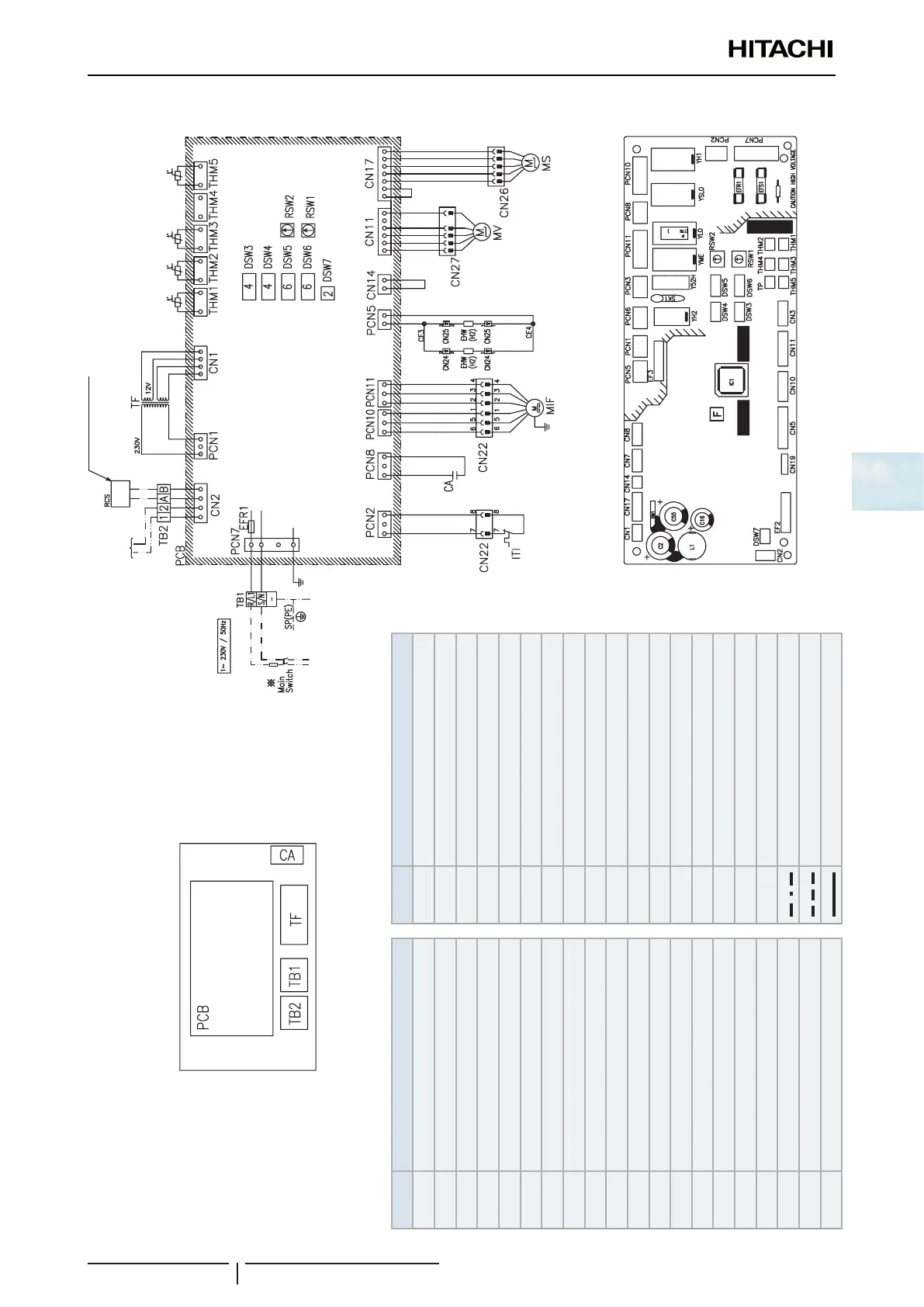
Wiring diagrams for the RPC-(3.0-6.0)FSN3E indoor units
Mark Name
CA Capacitor for Indoor fan
CN
21~26
Connector
DSW
3
Unit capacity code
DSW
4
Model
DSW
5
Refrigerant cycle nº
DSW
6
Unit code
DSW
7
Fuse recover/Remote control selector
EFR
1
Fuse
EFS
1
Fuse
EHW(H2) Electric heater
FS Float switch
ITI Internal thermostat for Indoor unit fan
MD Motor for drain discharge mechanism
MIF Motor for Indoor fan
MS Motor for automatic swing louver
MV Expansion valce
LED
1~3
Alarm code
PCB Printed circuit board
RCS Remote control switch
RSW
1
Indoor unit nº settings
Mark Name
RSW
2
Refrigerant cycle nº
SA Surge absorber
TB1 Terminal Block
TB2 Terminal block
CE3, 4 Connector
TF Transformer
THM
1
Inlet air thermistor
THM
2
Outlet air thermistor
THM
3
Liquid pipe thermistor
THM
5
Gas pipe thermistor
Y
H2
Relay for drain motor
Y
H1
Relay for HI fan motor tap
Y
ME
Relay for ME fan motor tap
Y
LO
Relay for LO fan motor tap
Y
SLO
Relay for SLO fan motor tap
Y
52H
Relay for electric heater
Field supplied
Field wiring
Earth wiring
Factory wiring
Operation
line DC5V
Wired controller
(Air
inlet)
(Air
outlet)
(Freeze
protection)
(Gas
piping)
Electrical control box
PCB sockets location
 Loading...

