4 Electrical and control settings
Wiring diagrams for indoor units and complementary systems
SMGB0099 rev.0 - 12/2016
174
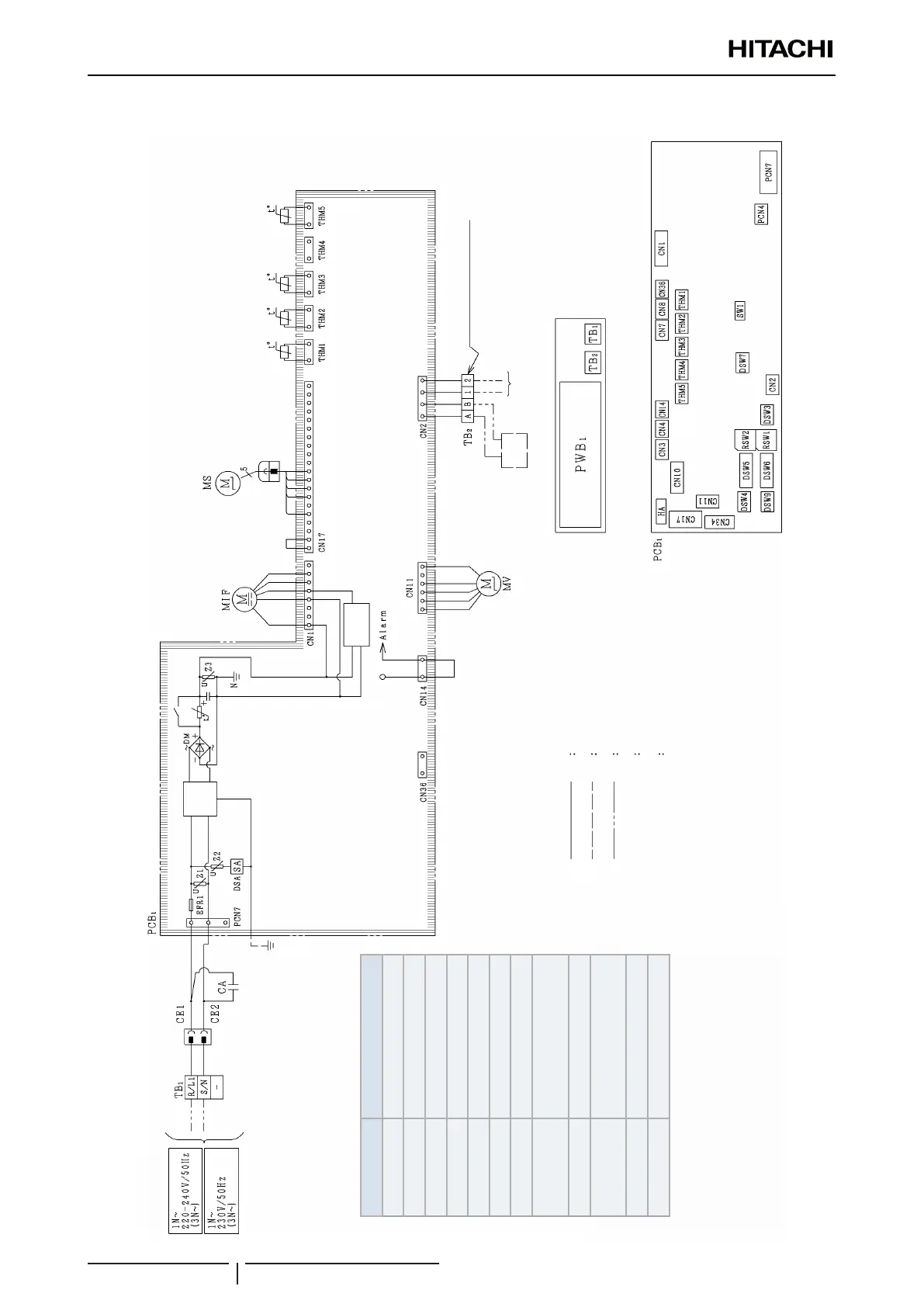
Wiring diagrams for the RPC-(1.5-6.0)FSN3 indoor units
Factory wiring
Earth wiring
Field wiring
Field connection
◆
Optional parts
►
Noise
lter
Supply
circuit
► Remote
control
switch
Operation
line DC5V
◆ Field connection
? NOTE
All the eld wiring and equipment must comply with local regulations.
Electrical control box
Printed circuit board
(Air
inlet)
(Air
outlet)
(Freeze
protection)
(Gas
piping)
Mark Name
CA Capacitor
TB1, 2 Terminal board
PCB1 Printed circuit board
PCN4,7 Connector on PCB
CN1~36 Connector on PCB
RSW1, 2 Rotary switch
DSW3~9, SW1 Dip switch for settings
MV
Micro-computer control
expansion valve
MIF Motor for Indoor fan
MS
Motor for automatic swing
louver
THM1~5 Thermistors
EFR1 Fuse
 Loading...

