38
P5416543
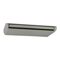
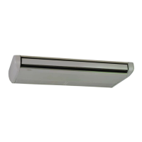
7.5 Wiring Connection
(1) The wiring connection for the indoor unit is
shown in the gure below.
(2) The wiring connection for electrical box is as
follows.
(a) Open the air inlet grille.
(b) Remove the electrical box cover.
(c) Connect the control cable, power source
cable and remote control switch cable.
7.6 Dip Switches Setting
(1) Turn OFF all the power supply of the indoor
unit and the outdoor unit before Dip Switch
setting. If not, the setting is invalid.
(2) The positions of Dip Switches on PCB are
shown in the gure below.
Tightly clamp wires by the cord clamp after the
wiring is completed to the terminal block. If not
completed, it may cause a re by biting wires.
(d) After the wiring is completed, attach the
electrical box cover again with care in
order not to bite wires.
Cap
Wire Connection
Rear Side
Cap
Wire Connectio
PCB1
Remote Control
Switch Cable
(White)
Terminal Block
(Black)
Power Source
Line
Earth Terminal
AB12
Terminal Block
(White)
Remote
Control
Switch
Cable
Transition Wiring
Between Indoor Units
Control
Cable
(Case that multiple indoor units are
operated by one remote control switch.)
This is not required for the simultaneous
operation of UTOPIA series at a maximum
of 4 indoor units.
1 2 3 4 5 6
ON
OFF
1 2 3 4 5 6
ON
OFF
DSW6 (Tens Digit)
RSW1 (Units Digit)
Setting
Position
Set by inserting
slotted screwdriver
into the groove.
Ex.) Set at No.16 Unit
DSW6
RSW1
Set No.1 Pin at ON side
Set at "6"
3
4
1
0
8
9
2
5
6
7
3
4
1
0
8
9
2
5
6
7
Before shipment, DSW6 and RSW1 are set at "0".
(a) for Units Supporting H-LINK II
The unit Nos. can be set for Max. 64 indoor units
(No.0~63).
(b) for Units Supporting H-LINK
The unit Nos. can be set for Max. 16 indoor units
(No.0~15).
(3) Unit No. Setting (RSW1 & DSW6)
The indoor unit No. of all indoor units are not
required. The indoor unit numbers are set by
the auto-address function. If the indoor unit
number setting is required, set the unit No.
of all indoor units respectively and serially by
following setting position. It is recommended
that the unit number setting start from “1”.
DSW4
DSW9
DSW7
DSW5
DSW6
RSW2
RSW1
DSW3
SW1
(Unit Model Code Setting)
RSW2 & DSW5
(Refrigerant Cycle No. Setting)
9
(Optional Function Setting)
RSW1 & DSW6
(Indoor Unit No. Setting)
DSW3
(Capacity Setting)
DSW7
(Fuse Recover)
Indoor Unit PCB
 Loading...