2-20
TC-12001
IN-THE-CEILING (DUCT)
14
P5414985
When the relative humidity of inlet or ambient air
H[FHHGVDSSO\DQ¿HOGVXSSOLHGDX[LOLDU\
drain pan beneath the indoor unit as shown in
Fig. 6.2.
Fig. 6.2 Auxiliary Drain Pan
'RQRWFUHDWHDQXSSHUVORSHRUULVHIRUWKHGUDLQ
SLSLQJVLQFHGUDLQZDWHUFDQÀRZEDFNWRWKH
XQLWDQGOHDNDJHWRWKHURRPZLOORFFXUZKHQWKH
unit operation is stopped.
Do not connect the drain pipe with sanitary or
sewage piping or any other drainage piping.
When the common drain piping is connected
with other indoor units, the connected position
of each indoor unit must be higher than the
common piping. The pipe size of the common
drain pipe must be large enough according to
the unit size and number of units.
$IWHUSHUIRUPLQJGUDLQSLSLQJZRUNDQGHOHFWULFDO
ZLULQJFKHFNWRHQVXUHWKDWZDWHUÀRZVVPRRWKO\
as in the following procedure.
&KHFNLQJZLWKWKH)ORDW6ZLWFK
a. 6ZLWFK21WKHSRZHUVXSSO\
b. Pour 2 or 2.5 liters of water into the drain
pan.
c. &KHFNWRHQVXUHWKDWWKHZDWHUÀRZV
VPRRWKO\RUZKHWKHUQRZDWHUOHDNDJH
occurs. When water cannot be found at the
end of the drain piping, pour another 2 liters
of water into the drain.
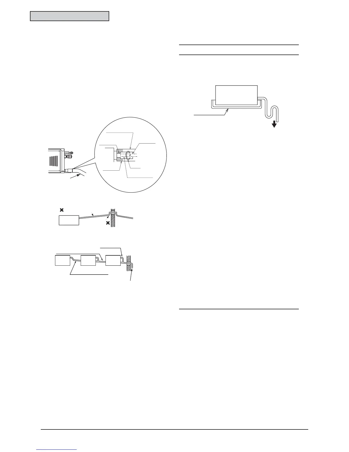
6. Drain Piping
The position of the drain piping connection is
shown in Fig. 6.1.
Prepare polyvinyl chloride pipe with a 32mm
outer diameter.
Fasten the tube to the drain hose with the
DGKHVLYHDJHQWDQGWKHIDFWRU\VXSSOLHG
clamp. The drain piping must be performed
ZLWKD'2:16/23(SLWFKRI
1/25 to 1/100.
Insulate the drain pipe after connecting the
drain hose.
Fig. 6.1 Drain Piping
NOTE
Indoor Unit
Auxiliary Drain Pan
(Field-Supplied)
To the Atmosphere
1/25 to 1/100
Down-Slope
Thermal Insulation
(Field-Supplied)
Drain Hose
Thermal
Insulation
Clamp
Polyvinyl
Chloride Tube
(Field-Supplied)
Seal
(Adhesive)
Drain Piping
Connection
1/25 to 1/100 Down-Slope
Common Drain Piping
This drain pipe shall be
separating from other pipes.
Incorrect: Upward Slope
Unit
Rising Part
Incorrect
Correct
 Loading...