5
ELECTRICAL WIRING
7
3. Provide a vinyl chloride tube, of a 26mm outer diameter
(C).
4. Connect a drain piping according to figure.
Do not create an upward slope from the unit.
Use vinyl chloride type adhesive for connecting the
drain pipe.
5. Tightly squeeze the drain hose with the wire clamp after
inserting the drain pipe into the drain hose completely.
6. Pour water onto the drain pan and check to ensure that
water flows smoothly.
5. ELECTRICAL WIRING
5.1. ELECTRICAL WIRING CONNECTION FOR INDOOR UNIT
The electrical wiring connection for the indoor unit is shown
below.
1. Connect the cable of an optional remote control switch
or an optional extension cable to the connectors on the
printed circuit board inside the electrical box through the
connecting hole in the cabinet.
2. Connect the power supply and earth wires to the
terminals in the electrical box.
3. Connect the wires between the indoor unit and the
outdoor unit to the terminals in the electrical box.
NOTE:
In the case of using PC-P1HE or PC-RLH11, remove
CN25 and CN12 (RPK-2.5~4.0) wiring. If not, the
system can not function.
■
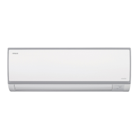
RPK-0.8 ~ 2.0
■
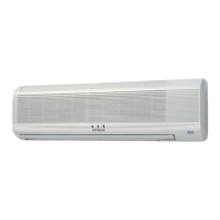
RPK-2.5 ~ 4.0
Provide a downward
slope to flow drain
water smoothl
Use adhesive tape
24 mm
VP20
Wiring Connection Terminal Board (TB)
PCB1
for Indoor
Unit
CN13
Remote Control
Switch
Connecting
Cable
Caulking Work
shall be performed
(Field-Wiring)
2 Wires Non-Polarity
Main Power Operating wires
Hole for Piping and Wiring
Electrical Box
Power
Source Line
Remote Control Switch
Connecting Cable for
PC-P1HE
Connecting to CN13 on PCB1
Terminal Board
Hole for the right side
Remote Control Switch
Screw for Earth Wire
Hole of Electrical Box
Operating line
Fasten cord by clamp
Hole for Piping and Wiring
Electrical Box
Power
Source Line
Remote Control Switch
Connecting Cable for
PC-P1HE
Connecting to CN13 on PCB1
Terminal Board
Hole for the right side
Remote Control Switch
Screw for Earth Wire
Hole of Electrical Box
Operating line
Fasten cord by clamp
 Loading...