Do you have a question about the Hitachi RWD-3.0NRWE-260S and is the answer not in the manual?
Provides introductory notes and copyright information.
Explains danger, caution, and note symbols used in the manual.
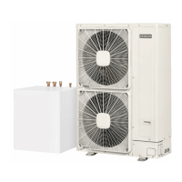
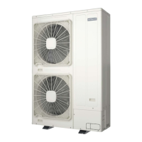
Details the classification and coding of YUTAKI units.
Lists specific safety precautions and warnings for operation.
Highlights critical instructions for installation and use of the system.
Explains key terms and conditions for electrical specifications.
Specifies nominal and operating voltage ranges for power supply.
Defines operating temperature limits for R410A models.
Defines operating temperature limits for R32 models.
Covers general notes and piping requirements for R32 refrigerant.
Details refrigerant piping and precautions for R410A.
Provides guidelines for water piping length and size.
Ensures power supply installation conditions are met.
Specifies wiring sizes for outdoor and indoor units.
Illustrates main power supply and communication wiring diagrams.
Identifies and explains the function of each button on the controller.
Explains common and comprehensive view icons for system status.
Guides through initial setup using Configuration Assistant or Advanced.
Describes the display elements of the controller's main screen.
Outlines the navigation structure for system settings and information.
Identifies and explains controller buttons for cascade systems.
Explains icons used in the cascade controller interface.
Guides through system setup for cascade controllers.
Describes the display elements of the cascade controller's main screen.
Outlines the navigation structure for system settings and information.
Details general maintenance procedures for outdoor and indoor units.
Provides introductory notes and copyright information.
Explains danger, caution, and note symbols used in the manual.
Details the classification and coding of YUTAKI units.
Lists specific safety precautions and warnings for operation.
Highlights critical instructions for installation and use of the system.
Explains key terms and conditions for electrical specifications.
Specifies nominal and operating voltage ranges for power supply.
Defines operating temperature limits for R410A models.
Defines operating temperature limits for R32 models.
Covers general notes and piping requirements for R32 refrigerant.
Details refrigerant piping and precautions for R410A.
Provides guidelines for water piping length and size.
Ensures power supply installation conditions are met.
Specifies wiring sizes for outdoor and indoor units.
Illustrates main power supply and communication wiring diagrams.
Identifies and explains the function of each button on the controller.
Explains common and comprehensive view icons for system status.
Guides through initial setup using Configuration Assistant or Advanced.
Describes the display elements of the controller's main screen.
Outlines the navigation structure for system settings and information.
Identifies and explains controller buttons for cascade systems.
Explains icons used in the cascade controller interface.
Guides through system setup for cascade controllers.
Describes the display elements of the cascade controller's main screen.
Outlines the navigation structure for system settings and information.
Details general maintenance procedures for outdoor and indoor units.
| Model | RWD-3.0NRWE-260S |
|---|---|
| Manufacturer | Hitachi |
| Category | Heat Pump |
| Cooling Capacity | 3.0 kW |
| Refrigerant | R410A |
| Coefficient of Performance (Heating) | 4.0 |
| Power Supply | 230V, 50Hz, 1-Phase |