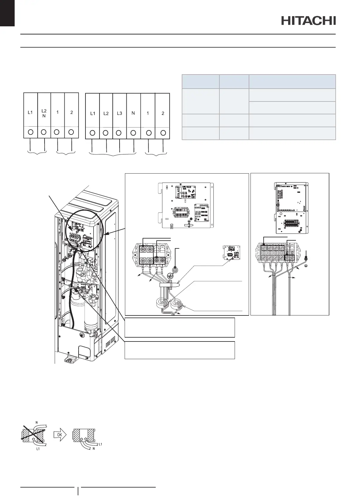
10.2 ELECTRICAL WIRING CONNECTION FOR OUTDOOR UNITS
The electrical wiring connection for the outdoor unit is shown in
Power supply
1~ 230V
Control cable
(5V)
Control cable
(5V)
Power supply
3N~ 400V
Table for Terminal Connection between units
Wiring System
Units type
Connection of terminals
Power Supply DC inverter
O.U. to O.U.
L1 to L1, L2 to L2, L3 to L3, N to N
I.U. to I.U.
L1 to L1, N to N
Operating DC inverter
O.U. to I.U. or I.U. to I.U.
1 to1, 2 to 2
Remote Control DC inverter
I.U. to I.U.
A to A, B to B
O.U.: Outdoor Unit; I.U.: Indoor unit
3
RST
MP
N
Electrical box
Control wiring
Screw (M5)
Screw (M5)
Screw (M4)
Screw (M4)
Earth terminal
Earth terminal
Earth wire
Communication
wiring
Earth wire
Ring core Yellow
Wind the wire 3 times
Power
source
wiring
Power
source
wiring
Detail of terminal block for power source
and control circuit.
circuit wiring)
power source wiring, control circuit wiring and earth wire)
Ring core Green
Wind the wire 4 times
? NOTE
InsertthepowersourcecablesL1andN(for1~230V50Hz)intothe
yellowringcore,coilingthemwith3turnsandxthecablesusingthe
cabletie(accessory).Asshowninnextgure,donotinsertthecables
fromdifferentsidesintotheringcore.
Insertthegroundcableintothegreenringcore,coilingthemwith4turns
andxthecablesusingthecabletie.
Electric wiring
PMML0545 rev.2 - 04/2021
14
EN

 Loading...